Industry Directory | Consultant / Service Provider
Samtec is recognized as the service leader in the connector industry. Most Samtec products fall into one of three categories: high speed (signal integrity), micro pitch, and rugged/power products.
92.jpg)
New Equipment | Industrial Automation
、 Nancy Lin Skype: +86-18020776786 Email: info@amikon.cn Tel: 86-18020776786(Whats App ) QQ :2851195456 IC693CBL300 is an I/O bus expansion cable also known as a “Wye cable”. It has a single male 25-pin D connector on one e
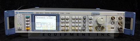
New Equipment | Test Equipment
80 dB, rise/fall time typ. 10 ns) Pulse generator integrated as standard Intuitive user interface with graphical display of signal flow (block diagram) Remote control via GPIB or LAN USB connectors (e.g. for keyboard, mouse, memor
Electronics Forum | Tue Feb 11 04:08:51 EST 2020 | majdi4
we have a problem : The connector is falling down in the second reflow. This connector is mounted in the first side. You can find attached the reflow profil we work with and a photo of the connector. We tryed with under_film but the connector is sti
Electronics Forum | Mon Feb 24 01:40:05 EST 2020 | sarason
Traditionally these connectors are riveted to the board on higher volume telecommunication applications. sarason

Used SMT Equipment | In-Circuit Testers
80 dB, rise/fall time SM-B8 = Pulse Modulator: on/off ratio >80 dB, rise/fall time SM-B9= Pulse Modulator: on/off ratio >80 dB, rise/fall time SM-B4 = Pulse Generator: only in conjunction with SM-B3/SM-B8/SM-B9; provides single, delayed and dou

Used SMT Equipment | In-Circuit Testers
80 dB, rise/fall time SMT-B19 = Rear Connectors for RF and LF: to replace front-panel connectors - See more at: https://www.testequipmentconnection.com/71751/Rohde_Schwarz_SMT03-B2-B4-B8-B19.php#sthash.YhEBmzSb.dpuf
Industry News | 2003-06-09 08:40:10.0
The Opening Session and Annual Meeting during SMTA International will be held on Tuesday, September 23.
Industry News | 2014-03-12 11:24:53.0
HITACHI's Sigma G5S modular mounter's Multi-function head now features lead clinching and tamping functionalities. Its lead clinching capability uses side-mounted lighting and machine vision to identify and precisely locate through-hole component leads. During placement/insertion, clinching simultaneously takes place to prevent the inserted component from falling out or becoming dislodged prior to soldering.
Technical Library | 2023-07-25 16:50:02.0
Some of the new handheld communication devices offer real challenges to the paste printing process. Normally, there are very small devices like 01005 chip components as well as 0.3 mm pitch uBGA along with other devices that require higher deposits of solder paste. Surface mount connectors or RF shields with coplanarity issues fall into this category. Aperture sizes for the small devices require a stencil thickness in the 50 to 75 um (2-3 mils) range for effective paste transfer whereas the RF shield and SMT connector would like at least 150 um (6 mils) paste height. Spacing is too small to use normal step stencils. This paper will explore a different type of step stencil for this application; a "Two-Print Stencil Process" step stencil. Here is a brief description of a "Two-Print Stencil Process". A 50 to 75 um (2-3 mils) stencil is used to print solder paste for the 01005, 0.3 mm pitch uBGA and other fine pitch components. While this paste is still wet a second in-line stencil printer is used to print all other components using a second thicker stencil. This second stencil has relief pockets on the contact side of the stencil any paste was printed with the first stencil. Design guidelines for minimum keep-out distances between the relief step, the fine pitch apertures, and the RF Shields apertures as well relief pocket height clearance of the paste printed by the first print stencil will be provided.
Technical Library | 2018-06-13 11:42:00.0
The art of screen printing solder paste for the surface mount community has been discussed and presented for several decades. However, the impending introduction of passive Metric 0201 devices has reopened the need to re-evaluate the printing process and the influence of stencil architecture. The impact of introducing apertures with architectural dimensions’ sub 150um whilst accommodating the requirements of the standard suite of surface mount connectors, passives and integrated circuits will require a greater knowledge of the solder paste printing process.The dilemma of including the next generation of surface mount devices into this new heterogeneous environment will create area ratio challenges that fall below todays 0.5 threshold. Within this paper the issues of printing challenging area ratio and their associated aspect ratio will be investigated. The findings will be considered against the next generation of surface mount devices.
GPD Global | https://www.gpd-global.com/co_website/pdf/doc/Dispense-System-Service-Guide-22290008G.pdf
items to the service panel: – Printer cord (to serial or parallel port on rear panel) – Ethernet connections – SMEMA cables - if only the incoming connector is used, connect it to the downstream (left) port and terminate the upstream (right) port


