Nov 03, 2021
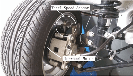
The wheel speed sensor is used to test the wheel speed of a car. For modern vehicles, wheel speed is essential. The vehicle dynamic control (VDC) system, vehicle electronic stability program (ESP), anti-lock braking system (ABS) all require wheel speed information. So the wheel speed sensor is one of the most critical sensors in modern society.
Considering the actual factors such as the working environment and the size of the wheel, the electro-magnetic induction sensor and hall type wheel speed sensor are mainly used.
How to Test the Wheel Speed Sensor
First, you should measure the clearance between the wheel speed sensor and the gear ring.
The normal standard value of front wheels should be 1.10 - 1.97mm, and that of rear wheels should be 0.42 - 0.80mm. If the clearance is too large, it will directly affect the accuracy of wheel speed sensor acquisition and data.
Then you check the output voltage part. Lift the vehicle, lift the wheels off the ground, and release the parking brake.
You remove the wire harness connector of the ABS wheel speed sensor and measure it.
You turn the wheel at 1r/s and use a multimeter to measure the output voltage. The front wheel should be 190 - 1140mV, and the rear wheel should be higher than 650mV.
If it meets the requirements, it means that the wheel speed sensor is working properly at this time.
Testing Steps
When the wheel speed sensor fails, the ABS module cannot receive the correct signal output. At this time, a fault code will be generated and there is a fault lamp flashing.
When we suspect that a sensor is faulty, we can make the following measurements to determine whether the sensor is faulty and fails to output the correct signal to the ABS module.
You should measure the voltage on the plug of the wheel speed sensor.
Hall type sensors have hall effect components, voltage regulator circuits, operational amplifiers and other electronic components that need a power supply and are put on.
By evaluating the voltage above the plug of the wheel speed sensor, you can directly determine whether the module has a voltage output, whether there is a problem with the module power supply, whether there is a short circuit.

Figure 2: The worker is measuring the voltage on the plug of the wheel speed sensor.
Then you should further judge whether the sensor is a two-line Hall-type wheel speed sensor.
You can use a multimeter to directly measure the sensor resistance. You cannot measure the resistance of the two-wire Hall-type wheel speed sensor which is infinity.
You measure it with a diode of a 0.3-0.7V tube drop. If you use a multimeter to measure the resistance, 1K-1.6K, this sensor will be a magnetoelectric sensor.

Figure 3: Some one is measuring the resistance of the wheel speed sensor by a multimeter.
You should measure the sensor signal.
The Hall type wheel speed sensor outputs the square wave pulse signal, which is an anti-interference type. Generally speaking, you should use an oscilloscope probe hook to clip the signal line, black clip to the body iron clip, and turn the signal plate.
Then you can see the waveform of 0.5V-1.5V square wave signal normally.
* Notes
Some cars are designed with power lines for signal output.
Some repair shops are not equipped with oscilloscopes, at this time you can only use a multimeter for the measurement.
The worker uses a black pen to put it on, a red pen to connect the signal line, and turns the signal disk by hand. The voltage on the multimeter display will have a fluctuation of 0.5V to 1.5V, which is normal.
If there is no signal output, you should check whether the signal disk is dirty, the sensor clearance, and the sensor condition.
At last, you should compare sensor data flows.
After entering the ABS module, you can read the data flow of the sensor, and start the car, conduct a road test.
After that, you should observe the data flow of the sensor and compare it with that of the other three wheel speed sensors. And this method can be applied to detect the sensor's occasional failure.

Figure 4: The mounting clearance of the wheel speed sensor.
The failure of the wheel sensor must cause your attention. Once the faults occur, it will lead to engine idle instability and acceleration performance decline.
What’s worse, in the vehicle starting or driving deceleration and parking, it is easy to cause instant pause, and even direct flameout. Therefore, when the wheel speed sensor fails, it must be repaired or replaced in time.
Working Principle of the Wheel Speed Sensor
Electro-Magnetic Induction Wheel Speed Sensor
It is designed based on the principle of electromagnetic induction.
When the wheel rotates, the rotor synchronized with the wheel rotates accordingly, and the teeth and clearances on the gear ring pass through the magnetic field of the sensor in turn.
The result is to change the magnetoresistance of the magnetic circuit, resulting in changes in the induced potential in the coil, generating potential pulses with a certain amplitude and frequency. Pulse frequency, or the number of pulses per second, reflects how fast the wheel rotates.
Hall Type Wheel Speed Sensor
It is designed using the principle of the Hall effect.
When the gear rotates, the density of magnetic field lines passing through the Hall element changes, thus causing the change of hall voltage. The Hall element will output a quasi-sine wave voltage (mV), which is then converted into a standard pulse voltage through an electronic circuit.
The frequency of the pulse, or the number of pulses per second, reflects the rotating speed of the wheel. And the wheel speed will be known through the frequency of the pulse.
Detection Methods

Figure 5: The wheel speed sensor is detected.
According to the working principle of the wheel speed sensor, it is obvious that if the wheel speed sensor is to be detected, its real working state must be simulated. For this, the following methods can be adopted.
If there are required experimental conditions, a motor-driven hub device can be prepared, and the sensor is installed in the corresponding position of the hub.
And you drive the motor, control the speed, simulate the actual working conditions, and observe the pulse waveform generated with the oscilloscope, analyze the pulse frequency.
Under normal circumstances, the faster the speed, the higher the pulse frequency is, the conversion between the wheel speed and frequency can also be carried out to reversely verify the quality and accuracy of the wheel speed sensor.
At this time, you should pay attention to the installation requirements of the wheel speed sensor, including the clearance, which will affect the actual waveform, and you must follow the installation requirements.
If you lack experimental equipment, you can directly measure it in a real vehicle. Definitely, the installation of the wheel speed sensor meets the requirements.
In static mode, you can use elevators or other equipment to lift the car, at this time the wheel speed sensor signal line is led out, and the oscilloscope is collected. Then you start the car, set a variety of actual speeds.
When the wheel is idling, pulse frequency can be detected, the principle of which is the same as above.
In dynamic and static mode, it’s the real road test. At this point, the wheel speed sensor signal line is led out from the car. When the wheel rotates, pulse frequency can be detected.