Nov 24, 2021
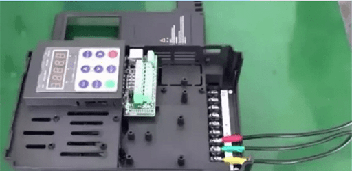
1. Main Circuit Wiring
1.1 Open the cover by squeezing the grooves on both sides of the VFD(variable frequency drive), remove the wire baffle, connect the terminals R, S, T to the power, connect the terminals U, V, W to the motor, and connect the earth wire at the ground symbol.
1.2 Connect the yellow, green and red power cables to the R, S and T in sequence.

Figure 1: R, S, T are connected to the power cables.
1.3 Connect the yellow, green and red power cables to the U, V and W in sequence.

Figure 2: U, V, W are connected to the motor.
1.4 After wiring, pay attention to check whether the power and motor are wrongly connected; whether the terminal crimping is firm; and whether the power line and the line to motor are aging, damaged or missed. After the wiring is completed, install the wire baffle and put the cover on the VFD, open the power switch to supply power to the VFD, which will display 50 Hz, then it can operate in normal.
2. Control Circuit Wiring
2.1 As shown in the figure 3, R is the braking resistor, R, S and T are the input terminals of the power supply, and the output terminals U, V and W are used to connect to the motor.

Figure 3: Typical wiring diagram of VFD
2.2
S1=forward rotation terminal
S2=reverse rotation terminal
S3=abnormal terminal
S5, S6, S7=terminals with different speeds
R1A= normally-open terminal
R1B=normally-closed terminal
R1C=common terminal
R2A, R2C=frequency detection terminal
2.3 Find the control terminal of the VFD and install two intermediate relays outside, which are KA1 and KA2 respectively. The wiring method is shown in the figure 4 below. When KA1 works, the VFD rotates forward, and when KA2 works, the VFD reverses. SB is the reset button. When there is an alarm, the VFD will stop. At this time, press RST to eliminate the alarm, and then restart the VFD.

Figure 4: Wiring method of forward rotating and reverse
2.4 If a potentiometer is used, the wiring method is shown in Figure 5 below. The output of the potentiometer is connected to the terminals 10, 2 and 3 of the frequency converter respectively. This is the output connected to the analog input. When the knob of the potentiometer is adjusted, the frequency of the frequency converter will change accordingly.

Figure 5: Wiring method of potentiometer
3. Summary for Main Circuit Wiring
3.1 The power supply should be connected to the input terminals R, S and T of the frequency converter, which must not be connected to the output terminals (U, V and W), otherwise the frequency converter will be damaged. After wiring, the waste wires must be cleaned, otherwise it may cause the abnormality and failure of the equipment which must be kept clean all the time. When drilling holes on the console, pay attention not to let fragments and powder into the VFD.
3.2 Do not connect anything other than the recommended braking resistor between terminals + and PR, or avoid short circuit.
3.3 If there is electromagnetic interference, and the input / output (main circuit) of the VFD contains harmonic components which may interfere with the communication equipment. Therefore, the interference can be minimized by installing radio noise filters (FR-BIF or FRBSF01 or FR-BLF).
3.4 Due to the charging current of parasitic capacitance in long distance wiring, the current limiting function of fast response will be reduced, and the instrument connected to the secondary side will be damaged. Therefore, the maximum wiring length should be less than the specified value. If the wiring length exceeds the specified value, PR.156 should be set to 1.
3.5 Do not install power capacitors, surge suppressors, and radio noise filters on the output side of the VFD. Otherwise, the VFD will fail or the capacitor and surge suppressor will be damaged.
3.6 In order to keep the voltage drop of VFD within 2%, the proper type of conductor should be used for wiring. When the connection distance between VFD and motor is long, especially in the case of low frequency output, the voltage of main circuit cable will drop, resulting in the torque drop of motor.
3.7 After the VFD starts, if you want to change the wiring, you must cut off the power for at least 10 minutes, and then check the voltage with a multimeter. This is because there is still dangerous high voltage on the capacitor for a period of time after cutting off the power.
4. Summary for Control Circuit Wiring
The control circuit can be divided into analog circuit and digital circuit.
4.1 Shielded wire or twisted pair wire should be used for terminal connection of control circuit, and the wiring must be separated from main circuit and high-current circuit (including 200V relay program circuit).
4.2 Because the frequency input signal of the control circuit is a small current, in order to prevent poor contact, the small signal contact should use two parallel nodes or twin contacts.
4.3 0.3-0.75 square meter cable is generally used for control circuit wiring.
5. Earth Wiring
5.1 Due to the leakage current in the VFD, in order to prevent electric shock, the VFD and motor must be grounded.
5.2 Special grounding terminal should be used for VFD grounding. Tinned crimping terminals should be used for the connection of earth wires. When tightening the screw, be careful not to damage the screw buckle.
5.3 There is no lead in the plated tin.
5.4 The grounding cable should be as thick as possible, which should not be less than the specified standard. The grounding point should be close to the frequency converter, and the grounding wire should be short.
6. Attention for VFD Wiring
6.1 The VFD has strong electromagnetic interference, which will interfere with the work of some equipment, so we can add a cable sleeve on the output cable of VFD.
6.2 The control line in the VFD or control cabinet should be at least 100 mm away from the power cable.
6.3 When you purchase a VFD, the manual will be accompanied. If not, you can download it from the website you purchased from. The contents of the manual are quite detailed, including product introduction, working principle, installation and debugging, etc.
The above is the basic wiring method. Hope to help you in the daily use and maintenance of the VFD.