Industry News | 2019-05-16 01:24:13.0
With the development of miniaturization of assembly components, the layout area and pattern design area of PCBs have also been continuously reduced, and PCB manufacturers are constantly updating the production process to conform to the development trend. The application of the resin plugging process has also become more and more extensive, and it has been used in HDI panels.
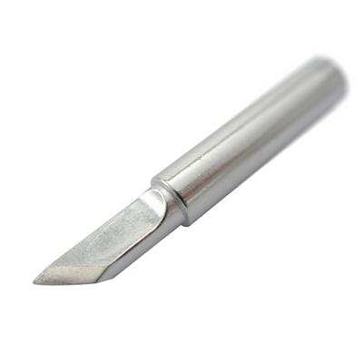
New Equipment | Solder Materials
900M series 900M-T-RT 900M-T-R 900M-T-K 900M-T-SI 900M-T-I 900M-T-S11 900M-T-4CF 900M-T-4C 900M-T-S10 900M-T-3CF 900M-T-3C 900M-T-2CF 900M-T-2C 900M-T-1.5CF 900M-T-1CF 900M-T-
Technical Library | 2020-08-27 01:22:45.0
Initially adopted internal specifications for acceptance of printed circuit boards (PCBs) used for wire bonding was that there were no nodules or scratches allowed on the wirebond pads when inspected under 20X magnification. The nodules and scratches were not defined by measurable dimensions and were considered to be unacceptable if there was any sign of a visual blemish on wire-bondable features. Analysis of the yield at a PCB manufacturer monitored monthly for over two years indicated that the target yield could not be achieved, and the main reasons for yield loss were due to nodules and scratches on the wirebonding pads. The PCB manufacturer attempted to eliminate nodules and scratches. First, a light-scrubbing step was added after electroless copper plating to remove any co-deposited fine particles that acted as a seed for nodules at the time of copper plating. Then, the electrolytic copper plating tank was emptied, fully cleaned, and filtered to eliminate the possibility of co-deposited particles in the electroplating process. Both actions greatly reduced the density of the nodules but did not fully eliminate them. Even though there was only one nodule on any wire-bonding pad, the board was still considered a reject. To reduce scratches on wirebonding pads, the PCB manufacturer utilized foam trays after routing the boards so that they did not make direct contact with other boards. This action significantly reduced the scratches on wire-bonding pads, even though some isolated scratches still appeared from time to time, which caused the boards to be rejected. Even with these significant improvements, the target yield remained unachievable. Another approach was then taken to consider if wire bonding could be successfully performed over nodules and scratches and if there was a dimensional threshold where wire bonding could be successful. A gold ball bonding process called either stand-off-stitch bonding (SSB) or ball-stitch-on-ball bonding (BSOB) was used to determine the effects of nodules and scratches on wire bonds. The dimension of nodules, including height, and the size of scratches, including width, were measured before wire bonding. Wire bonding was then performed directly on various sizes of nodules and scratches on the bonding pad, and the evaluation of wire bonds was conducted using wire pull tests before and after reliability testing. Based on the results of the wire-bonding evaluation, the internal specification for nodules and scratches for wirebondable PCBs was modified to allow nodules and scratches with a certain height and a width limitation compared to initially adopted internal specifications of no nodules and no scratches. Such an approach resulted in improved yield at the PCB manufacturer.
Industry News | 2003-06-13 10:10:58.0
By combining PacTech's electroless under bump metallization (UBM) processing with DEK's advanced mass imaging systems to create the solder bumps, users can implement a wafer-level, SMT-compatible flip chip assembly process.
Electronics Forum | Mon Nov 15 21:35:50 EST 1999 | Dave F
Bob Bob: Fortunately, you found this before you built-up a lot of product. Some thoughs and other drivel: 1 Use IPC-TM-650, Method 2.4.8 for copper peel with a Instron machine. Typical pad peel strength requirement for FR-4, 2 oz. copper is: 6 l
Electronics Forum | Thu Mar 04 17:10:19 EST 1999 | Earl Moon
| Our vendor proposed to supply us with shields made out of Cold Rolled Steel (CRS) electroplated with Sn (50 - 150 minches). Should I be concerned with solderability or are there a better alternatives to tin finish? | No matter the base metal, elec
Electronics Forum | Tue Jun 22 17:14:41 EDT 1999 | Dennis Fall
I am looking to apply 10-15�m of a conductive material that will withstand 280�C. Our product consists of an alumina substrate sputtered with NiCr (2000�) and Copper (2000�) and 15-60 �m of electroplated copper (all metals patterned on the substrae)
Electronics Forum | Wed Jun 23 10:21:25 EDT 1999 | Chrys Shea
| I am looking to apply 10-15�m of a conductive material that will withstand 280�C. Our product consists of an alumina substrate sputtered with NiCr (2000�) and Copper (2000�) and 15-60 �m of electroplated copper (all metals patterned on the substra
Electronics Forum | Wed Apr 21 17:11:05 EDT 1999 | Earl Moon
| Does anyone have any experience with soldering 50mil pitch BGA's that have a via in the pad, the size is .012 The via will be masked off on the bottom side of the board. Need to know what precautions or problems if any I might encounter. The proces
Electronics Forum | Wed Apr 21 19:09:10 EDT 1999 | Earl Moon
| | Does anyone have any experience with soldering 50mil pitch BGA's that have a via in the pad, the size is .012 The via will be masked off on the bottom side of the board. Need to know what precautions or problems if any I might encounter. The proc
.png)


