Technical Library | 2012-12-26 20:18:50.0
①Single side The basic flexible printed circuit board is used of substrate of single side pcb materials and coated coverlay after finishing printed. ②Double sided That is made of substrates of double sided printed circuit board with double surface coated coverlays after finishing printed. ③Single copper foil with double coverlays Single copper foil coated different coverlays with double surface after finishing printed. ④Air gap Laminating two single printed circuit board together with no glue and bare design to meet high flexibility requirements. ⑤Multilayer That is designed for three and above circuit layers by laminating single side printed circuit board or double sided printed circuit board. ⑥COF IC chips and electronic components are installed on the flexible circuit board directly. ⑦Rigid-Flexible PCB Combined to rigid PCB with supporting and flexible PCB with high flexibility.
A high speed micro via drilling system, the GS-600 incorporates a dual laser system for the highest throughput and hole quality. Capable of producing up to 900 holes/second, the hole diameters can range from 0.001" to 0.010". The GS-600 is compatib
Technical Library | 2020-09-02 22:14:36.0
The demand for miniaturization and higher density electronic products has continued steadily for years, and this trend is expected to continue, according to various semiconductor technology and applications roadmaps. The printed circuit board (PCB) must support this trend as the central interconnection of the system. There are several options for fine line circuitry. A typical fine line circuit PCB product using copper foil technology, such as the modified semi-additive process (mSAP), uses a thin base copper layer made by pre-etching. The ultrathin copper foil process (SAP with ultrathin copper foil) is facing a technology limit for the miniaturization due to copper roughness and thickness control. The SAP process using sputtered copper is a solution, but the sputtering process is expensive and has issues with via plating. SAP using electroless copper deposition is another solution, but the process involved is challenged to achieve adequate adhesion and insulation between fine-pitch circuitries. A novel catalyst system--liquid metal ink (LMI)--has been developed that avoids these concerns and promotes a very controlled copper thickness over the substrate, targeting next generation high density interconnect (HDI) to wafer-level packaging substrates and enabling 5-micron level feature sizes. This novel catalyst has a unique feature, high density, and atomic-level deposition. Whereas conventional tin-palladium catalyst systems provide sporadic coverage over the substrate surface, the deposited catalyst covers the entire substrate surface. As a result, the catalyst enables improved uniformity of the copper deposition starting from the initial stage while providing higher adhesion and higher insulation resistance compared to the traditional catalysts used in SAP processes. This article discusses this new catalyst process, which both proposes a typical SAP process using the new catalyst and demonstrates the reliability improvements through a comparison between a new SAP PCB process and a conventional SAP PCB process.
Industry News | 2016-05-21 08:04:11.0
Oak-Mitsui are proud to announce an expanded strategic partnership adding Oak Mitsui’s proprietary ABC (aluminum bonded copper) to Insulectro’s premier product portfolio including CAC (copper aluminum copper). By leveraging their bicoastal manufacturing locations, ABC will continue to manufacture its bonded product in Hoosick Falls, NY and Insulectro will continue to manufacture CAC at its facility in Lake Forest, CA. The complete line of Oak-Mitsui copper foils, on CAC and ABC, will be available in Insulectro’s inventory by June 17, 2016.

Bob Willis videos show you How to Do It each month. This month we talk about adhesion testing like copper foil, plated copper on PCBs or conformal coating adhesion to board assemblies. Adhesion testing can be used for many different materials and in
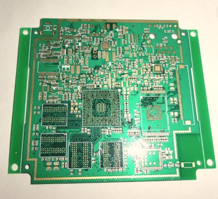
Layer: 8 layers Material: FR-4 Board Thickness: 0.6mm Surface Finish: Immersion Gold 1~4u Copper Thickness: 1/3 oz Impedance, 4/4mils width/spacing Layers: 2--36layers Max manufacturing size: 640mm*1100mm Copper foil thickness: 0.5OZ-13OZ M

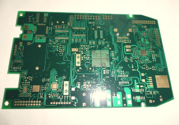
Layer: 2 Material: FR-4 Board Thickness: 1.6mm Surface Finish: HAL Copper Thickness: 2/2 oz Green Solder Mask Layers: 2--36layers Max manufacturing size: 640mm*1100mm Copper foil thickness: 0.5OZ-13OZ Min line width/space: 3mil/3mil Min
Layer: 6 layers Material: FR-4 Board Thickness: 1.0mm Surface Finish:ENIG Copper Thickness: 1 oz all layers Blind via L1~L2 and L1~L3 Layers: 2--36layers Max manufacturing size: 640mm*1100mm Copper foil thickness: 0.5OZ-13OZ Min line width
500⁰C) Compatible with multiple lamination cycles Standard PCB lamination cycles may be used Excellent for Laser Via formation Excellent CAF resistance Uses standard desmear and plating processes High Modulus: 1100 kpsi Lo
Technical Library | 2019-02-13 13:45:11.0
Development of information and telecommunications network is outstanding in recent years, and it is required for the related equipment such as communication base stations, servers and routers, to process huge amount of data in no time. As an electrical signal becomes faster and faster, how to prevent signal delay by transmission loss is a big issue for Printed Circuit Boards (PCB) loaded on such equipments. There are two main factors as the cause of transmission loss; dielectric loss and conductor loss. To decrease the dielectric loss, materials having low dielectric constant and low loss tangent have been developed. On the other hand, reducing the surface roughness of the copper foil itself to be used or minimizing the surface roughness by modifying surface treatment process of the conductor patterns before lamination is considered to be effective in order to decrease the conductor loss. However, there is a possibility that reduction in the surface roughness of the conductor patterns will lead to the decrease in adhesion of conductor patterns to dielectric resin and result in the deterioration of reliability of PCB itself. In this paper, we will show the evaluation results of adhesion performance and electrical properties using certain type of dielectric material for high frequency PCB, several types of copper foil and several surface treatment processes of the conductor patterns. Moreover, we will indicate a technique from the aspect of surface treatment process in order to ensure reliability and, at the same time, to prevent signal delay at the signal frequency over 20 GHz.

.gif)


