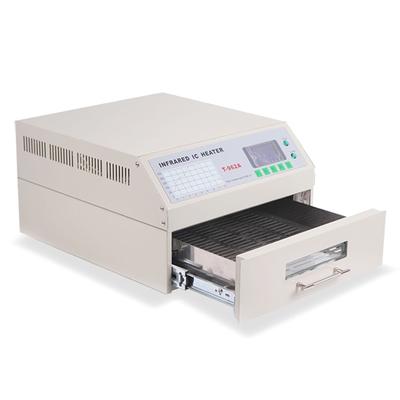
Quick Overview Max 300×320 mm soldering area INFRARED IC HEATER T-962A works automatically by micro-computer control. We adopt fast infrared radiation for heating and circular-wind to do temperature equalization, so the temperature in the drawer is
Industry News | 2009-12-07 18:08:56.0
Data I/O Corporation (NASDAQ: DAIO), the provider of manual and automated device programming solutions, today announced plans to debut its new FlashCORE III programming architecture at Productronica in Hall A2, Stand 329. This new technology will be at the core of every product to be highlighted at this key industry event, scheduled to take place 10th – 13th November at the Munich Trade Fair Center in Munich, Germany.
Electronics Forum | Mon Sep 14 04:36:53 EDT 1998 | Frank Ferdinandi
I am trying to find out if it is possible to wavesolder TSOP's. If so , what should the footprint be like, and how should the wavesolder process be set up ? Alternatively can PLCC's be wavesoldered ? I would greatly appreciate any help. Regards Fran
Electronics Forum | Tue Sep 15 08:53:48 EDT 1998 | Chrys
| I am trying to find out if it is possible to wavesolder TSOP's. If so , what should the footprint be like, and how should the wavesolder process be set up ? | Alternatively can PLCC's be wavesoldered ? | I would greatly appreciate any help. | Rega
Electronics Forum | Wed Mar 12 06:12:09 EDT 2008 | omidjuve
we have pcb here that has a strange footprint on it the details for the device that should be placed on this pcb is part no. PSD833F2-90MI it has 3 different packages PQFP52,PLCC52,TQFP64 and the one that was in the BOM of this board was PQFP52. bu
Electronics Forum | Thu Jul 22 04:34:54 EDT 1999 | George Verboven
| Which among the two profiling method is more reliable/accurate in getting the oven thermal profile? | | a) using a HIGH-TEMP solder wire then soldering the thermocouples onto the profile points of the board (e.g. component lead etc.) | | b) not s
Electronics Forum | Thu Jul 22 12:05:33 EDT 1999 | John Thorup
| | Which among the two profiling method is more reliable/accurate in getting the oven thermal profile? | | | | a) using a HIGH-TEMP solder wire then soldering the thermocouples onto the profile points of the board (e.g. component lead etc.) | | |
Electronics Forum | Mon Jul 26 11:20:40 EDT 1999 | Kevin Hussey
| | | Which among the two profiling method is more reliable/accurate in getting the oven thermal profile? | | | | | | a) using a HIGH-TEMP solder wire then soldering the thermocouples onto the profile points of the board (e.g. component lead etc.) |
Electronics Forum | Thu Jul 29 11:58:06 EDT 1999 | Greg Jones
| | | | Which among the two profiling method is more reliable/accurate in getting the oven thermal profile? | | | | | | | | a) using a HIGH-TEMP solder wire then soldering the thermocouples onto the profile points of the board (e.g. component lead e
Electronics Forum | Tue Feb 04 22:28:16 EST 2003 | davef
You could reduce the paste by about 70%. Solder balling and tombstoning will be the issues to fight. The drivers to these don't change with the component size. Use the fine SMTnet Archives for background. Aperture Size and Thickness of Solder Pas