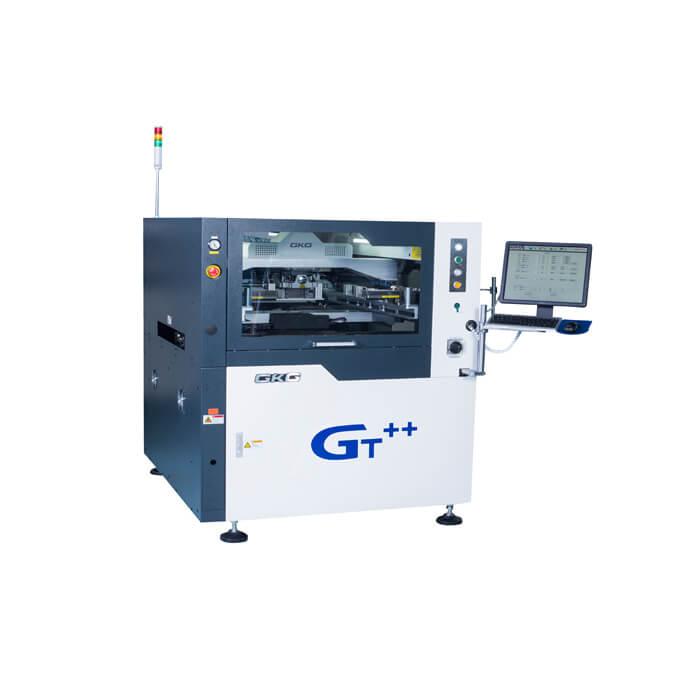
GKG GT++ SMT Stencil Printer Gross Power: 50W Voltage: 220V size: 1240*1410*1500mm Weight:1100Kg Product description: GKG GT++ SMT Stencil Printer,Gross Power: 50W,Voltage: 220V,size: 1240*1410*1500mm,Weight:1100Kg INQUIRY GKG GT+

GKG GT++ SMT Stencil Printer Gross Power: 50W Voltage: 220V size: 1240*1410*1500mm Weight:1100Kg Product description: GKG GT++ SMT Stencil Printer,Gross Power: 50W,Voltage: 220V,size: 1240*1410*1500mm,Weight:1100Kg INQUIRY GKG GT+

GKG GT++ SMT Stencil Printer Gross Power: 50W Voltage: 220V size: 1240*1410*1500mm Weight:1100Kg Product description: GKG GT++ SMT Stencil Printer,Gross Power: 50W,Voltage: 220V,size: 1240*1410*1500mm,Weight:1100Kg INQUIRY GKG GT+
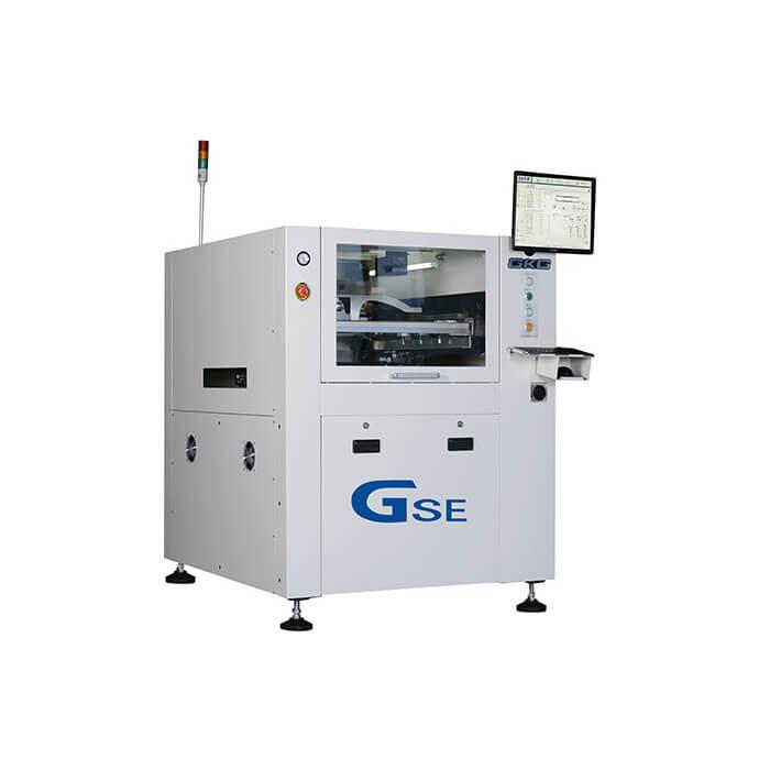
Flason SMT GKG GSE SMT Stencil Printer Gross Power: 50W Voltage: 220V size: 1158*1362*1463mm Weight:1000Kg Product description: GKG GSE SMT Stencil Printer Full Automatic-Good Price! Good Quality! Good Service! INQUIRY GKG GSE&

GKG GSE SMT Stencil Printer Gross Power: 50W Voltage: 220V size: 1158*1362*1463mm Weight:1000Kg Product description: GKG GSE SMT Stencil Printer,Gross Power: 50W,Voltage: 220V,size: 1158*1362*1463mm,Weight:1000Kg INQUIRY GKG GSE S
Industry News | 2011-08-30 20:52:38.0
SEHO North America, Inc. will showcase the PowerWave and GoSelective in Booth #113 at the upcoming IPC Midwest Conference & Exhibition.
Industry News | 2007-06-11 10:27:17.0
Building on the successful SM Series of fast, flexible placement systems, Dynatech Technology has added the Samsung Screen Printer SMP300 System - used by Samsung worldwide to assembly consumer and industrial products - to expand its turnkey SMT capability for North American assemblers.
Industry News | 2014-10-13 16:23:05.0
Nikon Metrology will be presenting Inspect-X 4.1 at Electronica Munich from 11-14 November, their latest release of the acquisition and analysis software for Nikon Metrology's range of X-ray and CT systems. The new technology provides improved real-time imaging and advanced BGA analysis.
Electronics Forum | Mon Oct 25 05:52:34 EDT 2010 | sachu_70
In csae you use 2 fiducial recognition, ensure that board fiducials are oriented across a diagonal and spaced far apart. Also, maintain a prefered dia between 1-2 mm for the fiducial on board to have have a better correction factor recorded during fi
Electronics Forum | Wed Nov 03 20:02:44 EST 1999 | Anthony Winston
Well John here is the situation: I need to place an infrared transistor (optical element) with a tolerance of +/-.003", this is not a problem. A lens is positioned over the optical element and snapped to the PCB via three holes that have a toleran


