
Mechatronic systems�s P20/P40 are flexible solutions for small and medium value series in the SMT-production. These machines were developed for assignments with claim for quick change of products, operating simplicity and reliability. Thanks to the
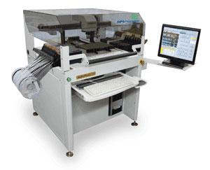
The most flexible pick and place system, the LS60, offers technologically advanced features with a 13" x 32" (330mm x 813mm) work area, 144 feeder positions where quick setup, ease of operation and high reliablity are paramount. The highest
Electronics Forum | Tue Oct 12 13:03:18 EDT 2021 | cunningham
Afternoon all, Do you use any special surface other that ESD matting when changing over matrix trays? We currently use a earthed wire trolley that we keep trays and MSD bags on and when replenishing stock its carried out on the trolley. Does anyon
Electronics Forum | Mon Feb 06 15:53:59 EST 2006 | Mike
Does anyone know where I can get the trays and carrousels for these old OKI machines? I contacted the guy in Florida who is selling these now and he has none. He has been saying they will be in two weeks for 18 months now. Any help is appreciated.
Used SMT Equipment | Pick and Place/Feeders
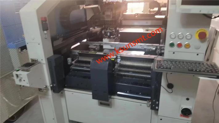
Machine Type YS12F Applicable PCB L510mm x W460mm to L50mm x W50mm Mounting accuracy Absolute accuracy(μ+3σ) +/-0.05mm/CHIP Mounting tact 20,000CPH(under our optimum condition) Component supply Tape reel, tray Number of

Used SMT Equipment | Chipshooters / Chip Mounters
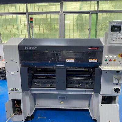
Product name: YV100X YAMAHA multi-functional chip mounter Product number: YV100X Products in detail YAMAHA multi-function placement machineYAMAHA YV100X substrate size: ATS20 (end to put) W -AT assembly: L460 * W250 (Max)/L50 * W50 (Min)sub
Industry News | 2016-11-07 16:28:47.0
GPD Global expands the performance of its automated dispense systems to run fundamental Pick & Place operations.
Industry News | 2023-08-17 14:26:37.0
Today, KINGSUN shares with you the common types and classifications of SMT mounters.
Parts & Supplies | Pick and Place/Feeders
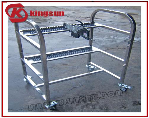
JUKI Feeder Storage Cart (Can be customized according to customer demand) Specification : Dimension: 800 x 600 x 1100mm, L x W x H Material: Full Stainless Steel Structure: 2 layers, 40pieces per layer With fou
Parts & Supplies | Pick and Place/Feeders
Product Description · * □ 32mm need to install special nozzle assembly · H15mm corresponding height · Identify the ball electrode · 107 corresponds to the maximum number
Technical Library | 2019-05-21 00:21:26.0
Continue to talk about the dust removal from temperature humidity test chamber. Cleaning and maintenance: 1) Pls remove internal impurities inisde chamber before operation. 2) The power distribution room should be cleaned at least once a year, and the dust can be removed by vacuum cleaner. 3) The exterior chamber must also be cleaned more than once a year, which can be wiped with soapy water. Inspection and maintenance of humidifier: The water storage in humidifier should be replaced once a month to ensure clean water quality, humidifying water tray should be cleaned once a month to ensure smooth flow of water. The inspection of over-temperature protector:during the test: If the temperature is over 20 ℃ ~ 30 ℃ than the maximum value setted,the power supply of the heater will stop, the "OVERHEAT" overt-emperature warning light will automatically turn on but the fan is still in operation, if the equipment runs without operator around,the operator should check the over-temperature protector in advance to ensure wether it has been setted properly before start [wet ball over-temperature protector set to 120 ℃].
Technical Library | 2020-08-27 01:22:45.0
Initially adopted internal specifications for acceptance of printed circuit boards (PCBs) used for wire bonding was that there were no nodules or scratches allowed on the wirebond pads when inspected under 20X magnification. The nodules and scratches were not defined by measurable dimensions and were considered to be unacceptable if there was any sign of a visual blemish on wire-bondable features. Analysis of the yield at a PCB manufacturer monitored monthly for over two years indicated that the target yield could not be achieved, and the main reasons for yield loss were due to nodules and scratches on the wirebonding pads. The PCB manufacturer attempted to eliminate nodules and scratches. First, a light-scrubbing step was added after electroless copper plating to remove any co-deposited fine particles that acted as a seed for nodules at the time of copper plating. Then, the electrolytic copper plating tank was emptied, fully cleaned, and filtered to eliminate the possibility of co-deposited particles in the electroplating process. Both actions greatly reduced the density of the nodules but did not fully eliminate them. Even though there was only one nodule on any wire-bonding pad, the board was still considered a reject. To reduce scratches on wirebonding pads, the PCB manufacturer utilized foam trays after routing the boards so that they did not make direct contact with other boards. This action significantly reduced the scratches on wire-bonding pads, even though some isolated scratches still appeared from time to time, which caused the boards to be rejected. Even with these significant improvements, the target yield remained unachievable. Another approach was then taken to consider if wire bonding could be successfully performed over nodules and scratches and if there was a dimensional threshold where wire bonding could be successful. A gold ball bonding process called either stand-off-stitch bonding (SSB) or ball-stitch-on-ball bonding (BSOB) was used to determine the effects of nodules and scratches on wire bonds. The dimension of nodules, including height, and the size of scratches, including width, were measured before wire bonding. Wire bonding was then performed directly on various sizes of nodules and scratches on the bonding pad, and the evaluation of wire bonds was conducted using wire pull tests before and after reliability testing. Based on the results of the wire-bonding evaluation, the internal specification for nodules and scratches for wirebondable PCBs was modified to allow nodules and scratches with a certain height and a width limitation compared to initially adopted internal specifications of no nodules and no scratches. Such an approach resulted in improved yield at the PCB manufacturer.
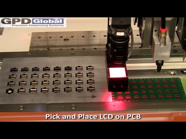
http://www.gpd-global.com GPD Global expands the performance of its automated dispense systems to run fundamental Pick & Place operations. The same automated fluid dispensing machine is capable of dispensing fluids and also Pick & Place simple compo
| https://www.feedersupplier.com/sale-13119374-smt-machine-parts-tray-fuji-nxt-mtu-m-tray-for-fuji-smt-pick-and-place-machine.html
SMT machine parts tray FUJI NXT MTU-M Tray for FUJI SMT pick and place machine Leave a Message We will call you back soon! Your message must be between 20-3,000 characters
Qinyi Electronics Co.,Ltd | https://www.qy-smt.com/shop/nxt-m-tray-nxt-m-tray-204142?page=82&category=1145&order=name+asc
Pricelist NxT M TRAY NxT M TRAY /shop/nxt-m-tray-nxt-m-tray-204142 ¥ 0.00 0.0 CNY ¥ 0.00 ¥ 0.00 This combination does not exist. ADD TO CART Inquiry Now > 1.Quality and


