Welcome to the next generation in PWB test solutions. We combine an exceptional team of technology and applications experts with HIOKI's industry-leading systems to enhance your reliability and to speed up your product development process.
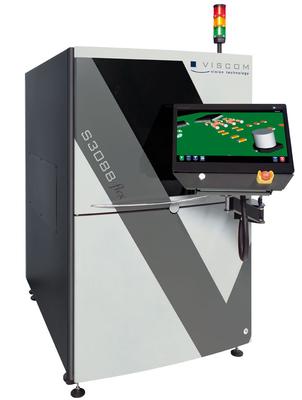
Extremely reliable, proven inspection for wave, reflow, pre-reflow and selective soldering. The S3088 flex AOI system was developed for reliable, economical defect detection and fast process optimization. From prototypes to large volume, this flexib
Electronics Forum | Wed Sep 29 09:29:47 EDT 2010 | swag
Take a few parts from the reel and look close at the parts to make sure the bottom surface of the leads is below the bottom surface of the body.
Electronics Forum | Thu Sep 30 11:30:46 EDT 2010 | babe7362000
Take a few parts from the reel and look close at > the parts to make sure the bottom surface of the > leads is below the bottom surface of the body. Yes I did that and they are below the body. I found the problem I think. The solder mask is abo
Industry News | 2019-11-12 13:01:33.0
MIRTEC has won an EM Best of Industry Award in the category of Automated Optical Inspection for its MV-6e OMNI. The award was presented to Bentec Distributor Accurex during a ceremony that took place 26 September at the Stellar Gymkhana in India. Bentec is the Managing Partner for UK/Ireland and India for MIRTEC.
Industry News | 2019-08-12 20:03:57.0
MIRTEC, ‘The Global Leader in Inspection Technology,’ today announced that it will display its award-winning 3D AOI, 2D AOI and SPI Inspection Systems in booth #1C55 with Mir Tech-win at the upcoming NEPCON ASIA (NEPCON SOUTH CHINA) exhibition, scheduled to take place August 28-30, 2019 at the Shenzhen Convention & Exhibition Center in China.
Technical Library | 2019-10-10 00:26:28.0
Voids are a plague to our electronics and must be eliminated! Over the last few years we have studied voiding in solder joints and published three technical papers on methods to "Fill the Void." This paper is part four of this series. The focus of this work is to mitigate voids for via in pad circuit board designs. Via holes in Quad Flat No-Lead (QFN) thermal pads create voiding issues. Gasses can come out of via holes and rise into the solder joint creating voids. Solder can also flow down into the via holes creating gaps in the solder joint. One method of preventing this is via plugging. Via holes can be plugged, capped, or left open. These via plugging options were compared and contrasted to each other with respect to voiding. Another method of minimizing voiding is through solder paste stencil design. Solder paste can be printed around the via holes with gas escape routes. This prevents gasses from via holes from being trapped in the solder joint. Several stencil designs were tested and voiding performance compared and contrasted. In many cases voiding will be reduced only if a combination of mitigation strategies are used. Recommendations for combinations of via hole plugging and stencil design are given. The aim of this paper is to help the reader to "Fill the Void."
Technical Library | 2024-06-23 22:03:59.0
The melting temperatures of most lead-free solder alloys are somewhat higher than that of eutectic Sn/Pb solder, and many of the alloys tend to wet typical contact pads less readily. This tends to narrow down the fluxing and mass reflow process windows for assembly onto typical organic substrates and may enhance requirements on placement accuracy. Flip chip assembly here poses some unique challenges. The small dimensions provide for particular sensitivities to wetting and solder joint collapse, and underfilling does not reduce the demands on the intermetallic bond strength. Rather, the need to underfill lead to additional concerns in terms of underfill process control and reliability. Relatively little can here be learned from work on regular SMT components, BGAs or CSPs.
The PCB Footprint Expert is a powerful CAD library development tool powered by our own proprietary CAD LEAP Technology (Libraries Enhanced with Automated Preferences). It is packed with very powerful advanced library management features that cuts foo

This animation shows the overview of programming and running of a MYDATA MY500 Jet Printing machine. Check the ''Jet Printing in detail'' video to see how Jet Printing works
Training Courses | ON DEMAND | | IPC-7711/7721 Trainer (CIT)
The Certified IPC-7711/7721 Trainer (CIT) courses recognize individuals as qualified trainers in the area of rework and repair of printed boards and electronic assemblies and prepares them to deliver Certified IPC-7711/7721 (CIS) training.
Events Calendar | Mon Apr 12 00:00:00 EDT 2021 - Mon Apr 12 00:00:00 EDT 2021 | ,
Europe Chapter Webinar: Tombstoning Components during Reflow Soldering - Causes & Cures
Events Calendar | Wed Dec 06 00:00:00 EST 2017 - Wed Dec 13 00:00:00 EST 2017 | Rolling Meadows, Illinois USA
X-Ray of PCBs Webtorial
---> SMT Express, Volume 3, Issue No. 6 - from SMTnet.com Volume 3, Issue No. 6 Friday, June 15, 2001 Featured Article Return to Front Page PCB Assembly Techniques by Harvey Twyman , University of Kent at Canterbury "I'm sure you
SMT Express, Volume 4, Issue No. 11 - from SMTnet.com Volume 4, Issue No. 11 Wednesday, November 20, 2002 Book Review Six Sigma for Electronics Design and Manufacturing by Sammy Shina Reviewed by Dave Fish (davef
| https://www.eptac.com/faqs/ask-helena-leo/ask/smt-components-during-reflow-float-off-pads
mass of solder and pulls the leads off the pads, resulting in no heel fillets. The component lead land areas need to be longer to accept this movement of the component on the large thermal pad
ASYMTEK Products | Nordson Electronics Solutions | https://www.nordson.com/en/divisions/efd/resource-center/solder-glossary-of-terms
. Pitch The center-to-center spacing of adjacent pads on a surface-mount board or leads on an electrical component. Plating A metal coating applied to a surface


