
New Equipment | Education/Training
This program is for experienced solderers seeking an in depth knowledge of the J-STD-001 Document. The course reviews this document and helps students learn how to interpret the criteria. Open and closed book exams are required after each module. Han
New Equipment | Fabrication Services
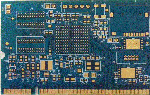
Minimum line width/space: 4mils Surface finish: immersion gold Board thickness: 1.20MM Minimum drilled hole diameter: 8mils Copper thickness: 0.5oz Special process : 0.40MM BGA , golden fingers
Electronics Forum | Fri Oct 26 05:03:17 EDT 2018 | farouk225
Hi everybody, I have a question about the minimum distance to leave beteween a non non-plated mounting hole with copper pads and the edge of the PCB. Is there any formula or rule to apply ? For example for a hole of diamater equals to 5.6mm which
Electronics Forum | Tue Feb 27 11:03:09 EST 2007 | Marcin
Hi All, Anybody knows what is the minimum clearance between through hole component and chip component? Problem description: On bottom side of my pcb are only 0603 chip components mounted on glue. One of the component is located very close to hole
Industry News | 2018-10-18 11:15:12.0
PCB Design and Layout Guidelines
Industry News | 2010-09-30 00:35:51.0
The new E revisions of IPC’s popular desk reference manuals, IPC-DRM-PTH, Through-Hole Solder Joint Evaluation Training & Reference Guide and IPC-DRM-SMT, Surface Mount Solder Joint Evaluation Training & Reference Guide have been released.
Technical Library | 2023-07-25 16:50:02.0
Some of the new handheld communication devices offer real challenges to the paste printing process. Normally, there are very small devices like 01005 chip components as well as 0.3 mm pitch uBGA along with other devices that require higher deposits of solder paste. Surface mount connectors or RF shields with coplanarity issues fall into this category. Aperture sizes for the small devices require a stencil thickness in the 50 to 75 um (2-3 mils) range for effective paste transfer whereas the RF shield and SMT connector would like at least 150 um (6 mils) paste height. Spacing is too small to use normal step stencils. This paper will explore a different type of step stencil for this application; a "Two-Print Stencil Process" step stencil. Here is a brief description of a "Two-Print Stencil Process". A 50 to 75 um (2-3 mils) stencil is used to print solder paste for the 01005, 0.3 mm pitch uBGA and other fine pitch components. While this paste is still wet a second in-line stencil printer is used to print all other components using a second thicker stencil. This second stencil has relief pockets on the contact side of the stencil any paste was printed with the first stencil. Design guidelines for minimum keep-out distances between the relief step, the fine pitch apertures, and the RF Shields apertures as well relief pocket height clearance of the paste printed by the first print stencil will be provided.
Training Courses | ON DEMAND | | IPC-6012 Trainer (CIT)
The Certified IPC-6012 Trainer (CIT) courses recognize individuals as qualified trainers in the area of design, fabrication and inspection of rigid printed boards and prepare them to deliver Certified IPC-6012 Specialist (CIS) training.
Training Courses | ON DEMAND | | IPC J-STD-001 Trainer (CIT)
The Certified IPC J-STD-001 Trainer (CIT) courses prepare individuals as qualified trainers in the area of producing high quality soldered interconnections and prepares them to deliver Certified IPC J-STD-001 Specialist (CIS) training.
SMT Express, Volume 2, Issue No. 3 - from SMTnet.com Volume 2, Issue No. 3 Thursday, March 16, 2000 Featured Article Return to Front Page Stencil Design for Mixed Technology Through-hole / SMT Placement and Reflow by William E. Coleman, Photo
| https://www.eptac.com/soldertip/soldertip-40-component-mounting-and-acceptability/
7.1.6 Component Mounting on page 7-15 of IPC-A-610 which describes the spacing between the board and the component. Also check the note which states that components cannot be tilted due to mating requirements with enclosures or panels, for example toggle switches, potentiometers, LCDs and LEDs
Imagineering, Inc. | https://www.pcbnet.com/capabilities/fabrication/tolerances/
.004″ for vias and a minimum of 0.006″ for component holes. VIPPO process allows + 0.006” (0.003” each side) Hole Size Our minimum finished hole size is 0.004″ laser, 0.005″ mechanical
winsouce.jpg)


