
New Equipment | Fabrication Services
Aluminum PCB & Metal Core PCB & LED PCB Circuit board Aluminium PCB are metal-based, copper-clad laminates with a good heat dissipation function. Usually, Aluminium PCB is refer to LED PCB board, which is the most important part of LED display and l
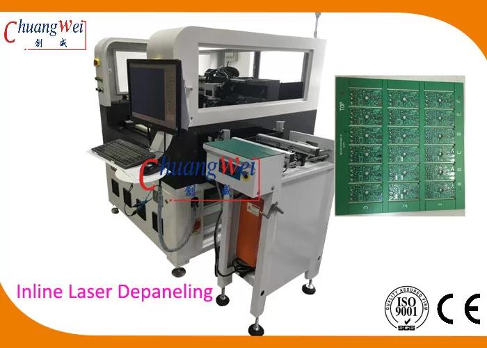
PCB Depaneling Machine Description: With the advent of new and high power plus lower cost UV lasers there is greater adoption of cutting of materials like printed circuit boards. This boards may be produced from fiber glass materials like FR4 or f
Electronics Forum | Fri Aug 03 05:55:25 EDT 2001 | mugen
tell ur IT guys, to stop the bulls**t!!! how u gonna write em, a ROI, when they haven't done THEIR job, of designing the system, and if em hav't design the system, how is anyone gonna know, how much money + manhours was spent, to complete the IT pro
Electronics Forum | Wed Aug 15 16:14:22 EDT 2001 | davef
Comparative Tracking Index [CTI]. In printed circuit board fabrication, CTI is a measure of the ability of the laminate surface to withstand tracking [carbonneous tracks on the surface, under wet contaminated conditions] across two electrodes placed
Industry News | 2018-10-18 11:07:09.0
What is the Maximum Panel Size for PCB Printing?
Technical Library | 2021-05-06 13:48:05.0
In this paper most commonly occurring Bare PCB defects such as Track Cut, Track short and Pad Damages are detected by Image processing techniques. Reference PCB without having any defects is compared with test PCB having defects to identify the defects and x-y coordinates of the center of the defects along with radii are obtained using Difference of Gaussian method and location of the individual type of defects are marked either by similar color or different colors. Result Analysis includes time taken for the inspection of a single defect, multiple similar defects, and multiple different defects. Time taken is ranging from 1.674 to 1.714 seconds if the individual type of defects are marked by different colors and 0.670 to 0.709 seconds if all the identified defects are marked by the same colors.
Technical Library | 2021-07-20 20:02:29.0
During the manufacturing of printed circuit boards (PCBs) for a Flight Project, it was found that a European manufacturer was building its boards to a European standard that had no requirement for copper wrap on the vias. The amount of copper wrap that was measured on coupons from the panel containing the boards of interest was less than the amount specified in IPC-6012 Rev B, Class 3. To help determine the reliability and usability of the boards, three sets of tests and a simulation were run. The test results, along with results of simulation and destructive physical analysis, are presented in this paper. The first experiment involved subjecting coupons from the panels supplied by the European manufacturer to thermal cycling. After 17 000 cycles, the test was stopped with no failures. A second set of accelerated tests involved comparing the thermal fatigue life of test samples made from FR4 and polyimide with varying amounts of copper wrap. Again, the testing did not reveal any failures. The third test involved using interconnect stress test coupons with through-hole vias and blind vias that were subjected to elevated temperatures to accelerate fatigue failures. While there were failures, as expected, the failures were at barrel cracks. In addition to the experiments, this paper also discusses the results of finite-element analysis using simulation software that was used to model plated-through holes under thermal stress using a steady-state analysis, also showing the main failure mode was barrel cracking. The tests show that although copper wrap was sought as a better alternative to butt joints between barrel plating and copper foil layers, manufacturability remains challenging and attempts to meet the requirements often result in features that reduce the reliability of the boards. Experimental and simulation work discussed in this paper indicate that the standard requirements for copper wrap are not contributing to the overall board reliability, although it should be added that a design with a butt joint is going to be a higher risk than a reduced copper wrap design. The study further shows that procurement requirements for wrap plating thickness from Class 3 to Class 2 would pose little risk to reliability (minimum 5 μm/0.197 mil for all via types).Experimental results corroborated by modeling indicate that the stress maxima are internal to the barrels rather than at the wrap location. In fact, the existence of Cu wrap was determined to have no appreciable effect on reliability.
Events Calendar | Wed Sep 11 00:00:00 EDT 2024 - Wed Sep 11 00:00:00 EDT 2024 | San Diego, California USA
San Diego Chapter In-Person Event: Reclaiming Precious Metal from SMT Scrap
Career Center | , USA | Sales/Marketing
Silicon Forest Electronics is looking for an Outside Account Executive. This is a company that is financially solid, growing rapidly and has even stronger future growth prospects. It is also a company that values its employees and fosters a team-orie
Career Center | Home Based, Utah USA | Sales/Marketing
VP of Business Development, Corporate Accounts 1099 arrangement, a contracted sales representative, home based Do you want the opportunity to make unlimited income? Do you want the freedom to decide your work schedule? Do you want to be your own
Career Center | vestal, New York USA | Quality Control
Over 7 years of experience as lead quality engineer in the filed of SMT. Extensive knowledge on Universal GSM,GC60 and GC120 Machines. worked on IBM Rational and Mercury Winruner testing tools.
Career Center | Stouffville, Ontario Canada | Engineering,Maintenance,Management,Production,Purchasing,Technical Support
Innovation/Creativity Cost Saving Strategies Employee Motivation Customer Service Focus Program, Repair and Maintenance New Product Development Continuous Improvement Training & Development Process Planning & Labour O
ORION Industries | http://orionindustries.com/pdfs/formex.pdf
+ HIGH VOLTAGE ARC TRACKING-IN/MIN UL 746A 0.0 0.0 0.0 0.0 0.0 HOT WIRE IGNITION-SECONDS UL 746A 6+ 7 9 12 12 COMPARATIVE TRACKING INDEX-VOLTS ASTM D-3638 600+ 600+ 600+ 600+ 600


