Overview The USB 2.0 Mass Storage Design Platform is a complete, integrated solution dedicated to use in wide range of USB based Mass Storage Devices like portable flash memory device, digital audio player, card reader or digital camera. Features
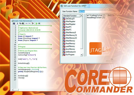
Device control via internal JTAG access - processor and FPGA cores While many ICs are equipped with a JTAG (IEEE Std. 1149.1) boundary-scan register (BSR), a significant number of microprocessors and DSPs can be found with deficient or even non-exi
Used SMT Equipment | Turnkey Lines
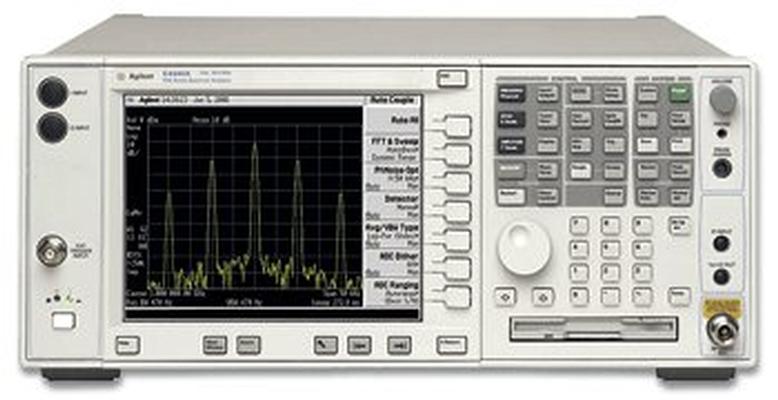
US4222/MY4100. 122 80 MHZ Bandwidth Digitizer 123 Switchable MW preselector bypass 124 Y-axis video output 140 40 MHZ Bandwidth Digitizer 1A7 PSA Series ISO 17025 compliant calibration with test data 1CM Rackmount Kit
Used SMT Equipment | In-Circuit Testers
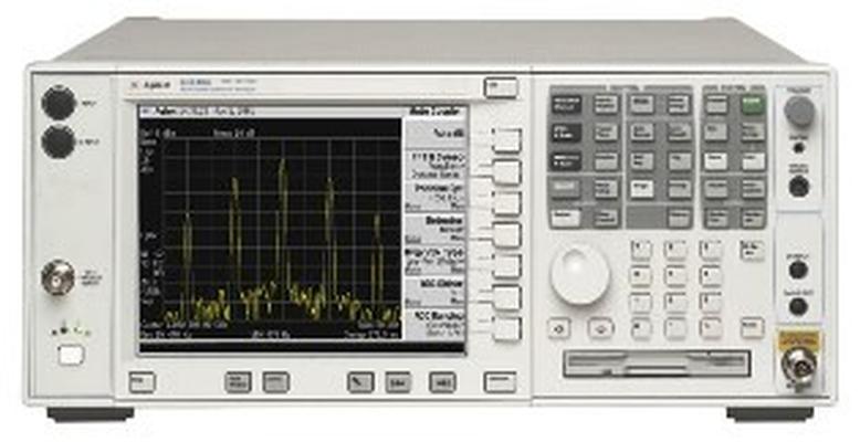
US4222/MY4100. 122 80 MHZ Bandwidth Digitizer 123 Switchable MW preselector bypass 124 Y-axis video output 140 40 MHZ Bandwidth Digitizer 1A7 PSA Series ISO 17025 compliant calibration with test data 1CM Rackmount Kit
Industry News | 2001-12-03 07:45:41.0
Motorola to Preview Next-Generation 0.10 micron CMOS Technology and New Gate Dielectric Material at World's Leading Semiconductor Device Conference
Technical Library | 1999-05-07 10:13:38.0
This paper will review the device physics governing the operation of the industry standard ETOX™ flash memory cell and show how it is ideally suited for multiple bit per cell storage, through its storage of electrons on an electrically isolated floating gate and through its direct access to the memory cell.

Demonstration of JTAG Live™ CoreCommander software. CoreCommander offers JTAG control of µprocessors, and DSPs via core debug access. The tool's routines take control of key processor core (e.g. ARM, PPC, X-scale, Cortex etc.) functions using the bui
GPD Global | https://www.gpd-global.com/co_website/pdf/doc/Dispense-System-Service-Guide-22290008G.pdf
guided relays, servo control relays, and a safety gate monitor. Use the table below for quantity of each item by dispenser model. For diagram details, refer to the Safety Package Circuit Diagrams in the Mechanical & Electrical Reference document. Table 1


