Industry Directory | Consultant / Service Provider / Manufacturer
Providing production and prototype, SEC offers advanced technologies like LED thermal management, heavy copper, PTFE for RFMW, open and internal cavities and blind and buried vias that are certified to a diverse set of industries.
Industry Directory | Manufacturer
Eastech Group was established in 2006. It is a professional research and development, production and sales of high precision multilayer circuit board manufacturers(National High-tech Enterprise).
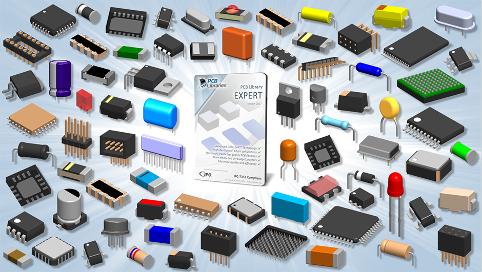
The PCB Footprint Expert is a powerful CAD library development tool powered by our own proprietary CAD LEAP Technology (Libraries Enhanced with Automated Preferences). It is packed with very powerful advanced library management features that cuts foo
New Equipment | Solder Materials
I.C.T | Antioxidant Silver Soldering Tin Lead Free Solder Bar for Solder Wave ❙ Introduction I.C.T has been working with suppliers to develop environmentally friendly lead-free solders and related materials and can now supply products that delive
Industry News | 2018-10-18 09:45:34.0
How to Export Gerber Files from Eagle
Industry News | 2018-10-18 11:13:35.0
PCB Outline Layer And Keep-out Polygon Clearance
The PCB Footprint Expert is a powerful CAD library development tool powered by our own proprietary CAD LEAP Technology (Libraries Enhanced with Automated Preferences). It is packed with very powerful advanced library management features that cuts foo

In the world of makers, people enjoy the fun of designing and developing hardware/ software, even final electronic products. They will not concentrate a lot on the cost and manufacturability. But it is quite different from lab to factory, when it com
SMTnet Express, June 27, 2019, Subscribers: 32,092, Companies: 10,819, Users: 24,882 Advanced Cu Electroplating Process for Any Layer Via Fill Applications with Thin Surface Copper Credits: MacDermid Inc. Copper-filled micro-vias are a key
PCB Libraries, Inc. | https://www.pcblibraries.com/forum/RSS_copper-on-one-side-of-through-hole_topic1972.xml
. It requires two slotted through holes with no copper on the top side and copper pads on the bottom layer. I have created this pattern several times in FP Designer and it looks good until I try to reload the part either by reloading the FPX or switching to a different part and coming back
| http://etasmt.com/cc?ID=te_news_industry,26764&url=_print
. A typical metal core PCB layout includes: The top layer: Soldermask The second layer: Circuit layer, which is copper foil The third layer


.gif)
