Industry News | 2013-06-10 10:36:15.0
Conductive Compounds Inc. is now ISO 9001: 2008 Registered
Quantifies mark quality for printed, etched, peened, or ink-jet-marked Data Matrix symbols on any material.
Flake & Powders for die-Attach adhesives and thick film inks. (Silver, Copper, Silver-Palladium, Platinum)
Parmod�, Parelec Inc�s patented conductive ink technology, enables the formation of continuous-phase pure metallic conductors at relatively low temperature�making them suitable for application to polymer substrates. Parmod� inks, pastes and toners ca
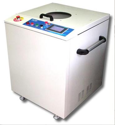
G 5003 - LR Ink Mixer and Defoamer (Air Bubble Remover) R&D for Best Mixing Solution: Ink for Printed Circuit Boards, AB paste and Ag (Silver) paste mixing and defoaming solution. Great use for: PCB Factory, Glass Panel Factory, Photoelectric Ind
Industry Directory | Manufacturer's Representative
Specialty materials for SMT Assembly. Solder Paste, Spheres, Tac Fluxes, Flip Chip Fluxes, Solder wi
Technical Library | 2012-12-27 14:35:29.0
Printed Electronics is generally defined as the patterning of electronic materials, in solution form, onto flexible substrates, omitting any use of the photolithography, etching, and plating steps commonly found within the Printed Circuit Board (PCB) industry. The origins of printed electronics go back to the 1960s, and close variants of several original applications and market segments remain active today. Through the 1980s and 1990s Printed Electronic applications based on Membrane Touch Switch and Electroluminescent lighting technologies became common, and the screen printed electronic materials used then have formed the building blocks for many of the current and emerging technologies and applications... First published in the 2012 IPC APEX EXPO technical conference proceedings.
Technical Library | 2017-11-22 12:38:51.0
The use of copper foils laminated to polyimide (PI) as flexible printed circuit board precursor is a standard practice in the PCB industry. We have previously described[1] an approach to very thin copper laminates of coating uniform layers of nano copper inks and converting them into conductive foils via photonic sintering with a multibulb conveyor system, which is consistent with roll-to-roll manufacturing. The copper thickness of these foils can be augmented by electroplating. Very thin copper layers enable etching fine lines in the flexible circuit. These films must adhere tenaciously to the polyimide substrate.In this paper, we investigate the factors which improve and inhibit adhesion. It was found that the ink composition, photonic sintering conditions, substrate pretreatment, and the inclusion of layers (metal and organic) intermediate between the copper and the polyimide are important.
Technical Library | 2018-10-24 18:04:12.0
Polymer Thick Film (PTF)-based printed electronics (aka Printed Electronics) has improved in durability over the last few decades and is now a proven alternative to copper circuitry in many applications once thought beyond the capability of PTF circuitry. This paper describes peak performance and areas for future improvement.State-of-the-art PTF circuitry performance includes the ability to withstand sharp crease tests, 85C/85%RH damp heat 5VDC bias aging (silver migration), auto seat durability cycling, SMT mandrel flexing, and others. The IPC/SGIA subcommittee for Standards Tests development has adopted several ASTM test methods for PTF circuitry and is actively developing needed improvements or additions. These standards are described herein. Advantages of PTF circuitry over copper include: varied conductive material compositions, lower cost and lower environmental impact. Necessary improvements include: robust integration of chip and power, higher conductivity, and fine line multi-layer patterning.
Technical Library | 2023-03-13 19:27:13.0
10%) and mean strains (>30%). A trace width effect is found for the fatigue behavior of 1 mm vs 2 mm wide specimens. The input specimen-characteristic curves are trace-width dependent, and the model predicts a decrease in Nf by a factor of up to 2 for the narrower trace width, in agreement with the experimental results. Two different methods are investigated to generate the rate of normalized resistance increase curves: uninterrupted fatigue tests (requiring ∼6–7 cyclic tests), and a single interrupted cyclic test (requiring only one specimen tested at progressively higher strain amplitude values). The results suggest that the initial decrease in normalized resistance rate only occurs for specimens with no prior loading. The minimum-rate curve is therefore recommended for more accurate fatigue estimates.


