I received a buck-boost DCDC board with an optical sensor from NextPCB, so I mounted the components and measured the efficiency.
Table of contents
- Board received from NextPCB
- Solder paste printing
- Mounting of parts
- Reflow
- operation check
- Attaching the pin header
- measure the characteristics
- Buck-boost DCDC converter completed!
Board received from NextPCB
About a week after ordering, the board and metal mask arrived.
This ad is real! NextPCB $0 PCB offers a free PCB prototype with a thickness of 1.6 mm (or 1 and 1.2 mm) with all parameters, i.e. solder-mask, metallized holes and Tg130 as well as overprint with descriptions in this PCB quote page. The board has a maximum size of 100 × 100 mm. That's quite a lot.
The board this time has rounded corners .
The silk is also beautifully printed.
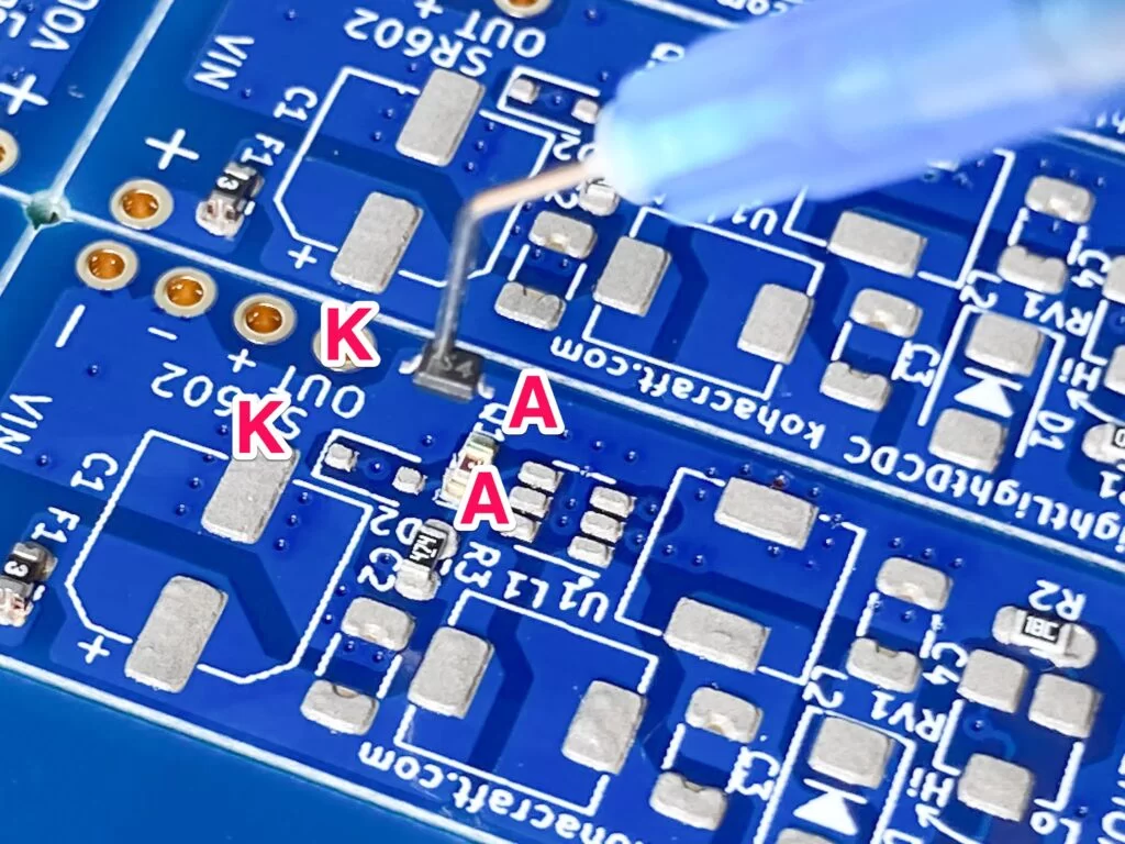
This is the merit of making a metal mask with NextPCB. A 0805 capacitor is mounted on the arrow pad. The pads are concave rather than square .
KiCad data does not specify such processing, but NextPCB processes it like this.I think it's a very nice service.
Solder paste printing
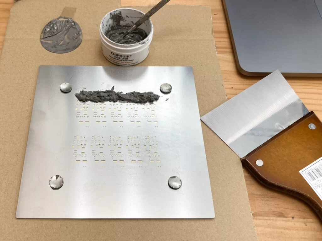
Place the board on top of the cardboard.
Place the metal mask on top of it and insert thumbtacks into the pre-drilled holes to fix the board and the metal mask.This ensures that the substrate and metal mask are perfectly aligned.
Choose a putty knife to use for printing solder paste. I've bought and tried many different types of putty, but this time I have a printing width of 10 cm.
Place the solder paste on the far side of the metal mask .
Print solder paste with flexible putty. The tip of this flexible putty is processed with very high precision, leaving almost no solder paste on the metal mask.
There was no misalignment, and the solder paste could be printed very neatly.
Polarized components always have the same orientation inside the tape for surface mount components.
By setting the direction of this component and the direction of mounting the component on the board in the same direction, the component can be mounted in the same direction as the component is picked up.
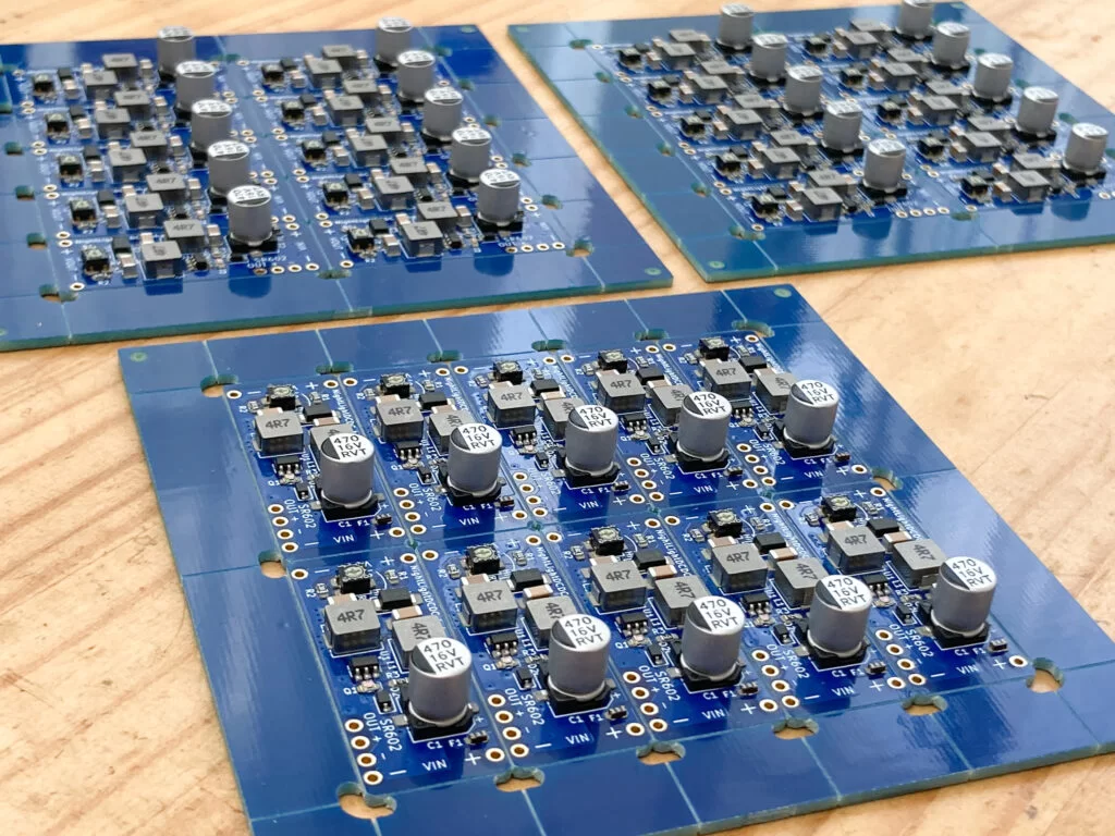
The board made by NextPCB has 10 boards mounted on it. We are going to mount 10 of the same parts, but by using HAKKO 394-01 and directly picking up the parts from the tape, we can mount them very quickly.
For the nozzle, I use this that has higher adsorption power than the genuine product and is easier to mount.
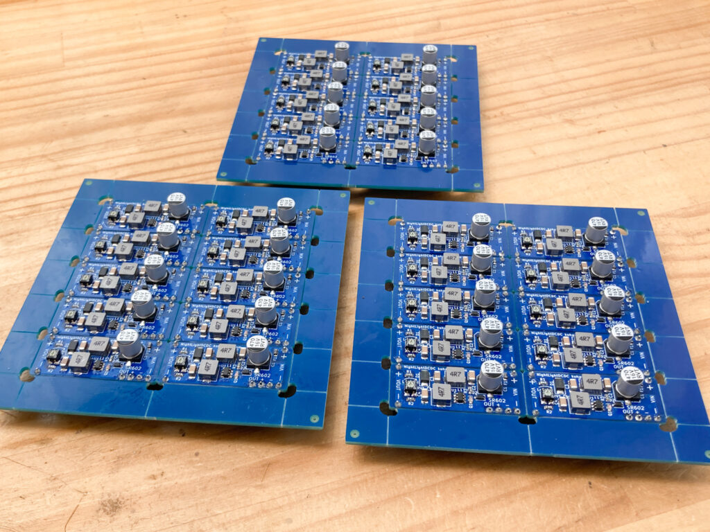
Mounting of parts is completed.
Reflow
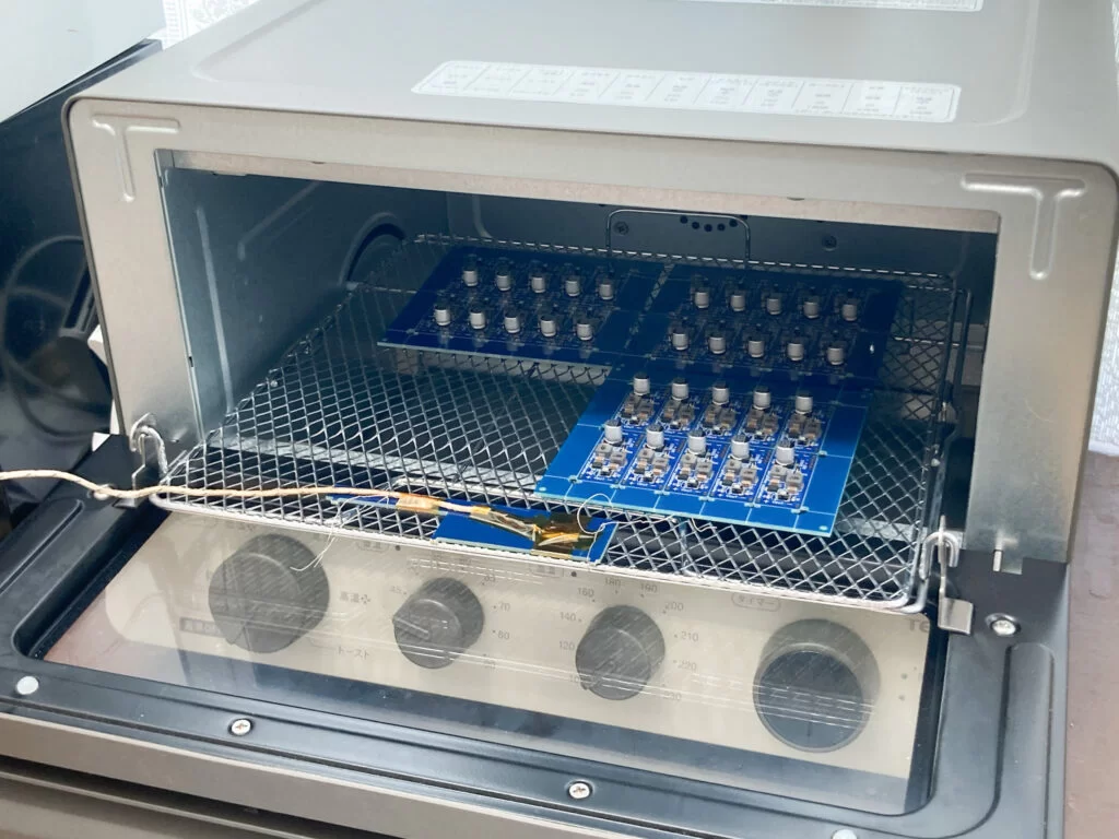
Reflow is done in a convection oven that can heat the inside of the cabinet evenly with warm air. Tescom's convection oven TSF601 can change the set temperature even in the middle of heating . profile of the solder paste.
A thermocouple thermometer sensor is placed inside the oven, and the temperature inside the oven is adjusted while looking at the thermometer.
After the reflow is finished, cool it with a fan.
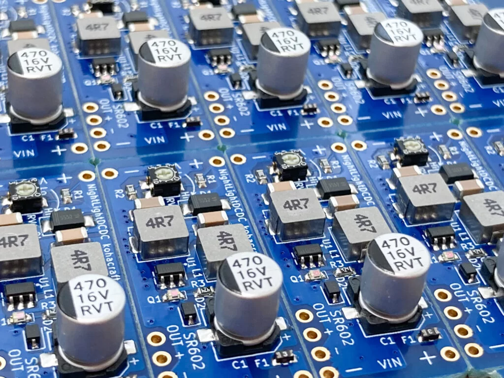
Reflow is complete. It reflows nicely.
Operation check
I made a measuring jig using a test probe. Power supply and output voltage can be monitored via test probes
All DCDC converters were confirmed to work properly.
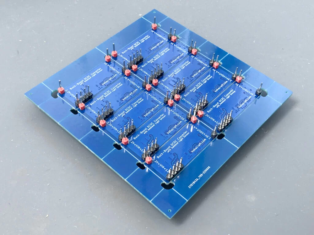
Attaching the pin header
This DCDC converter is supposed to be used by inserting it into a breadboard .
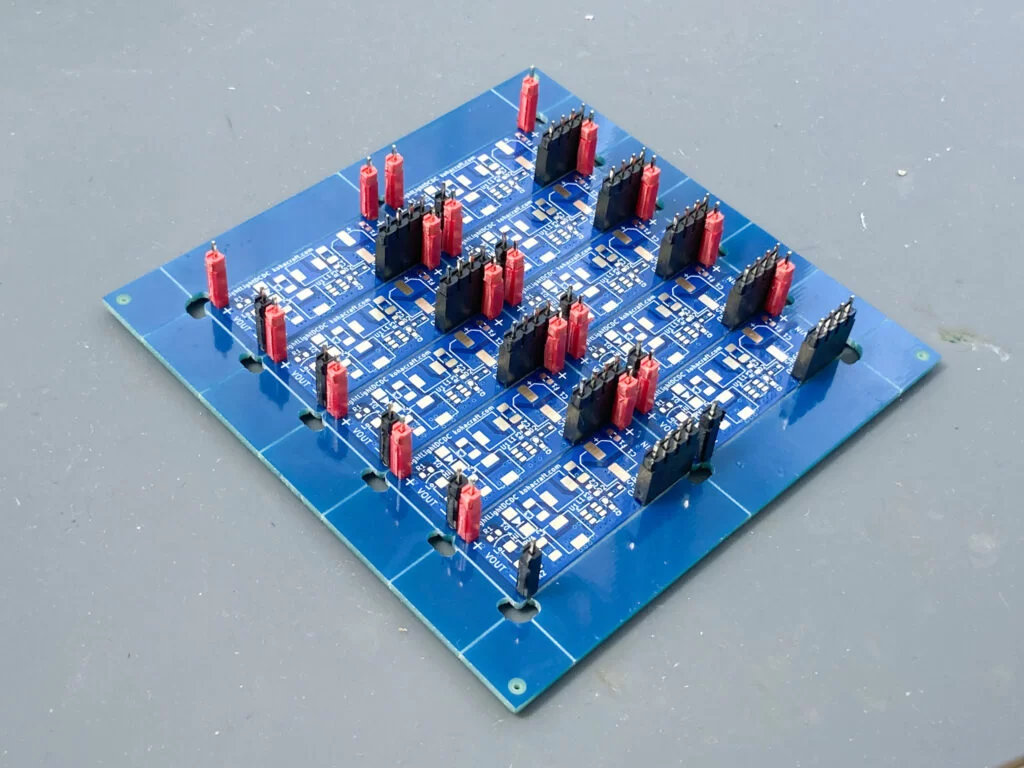
Solder the pin socket to the board without parts made by NextPCB
On top of this, place the board to solder the pin headers.
I was able to solder straight without bending the pin header.
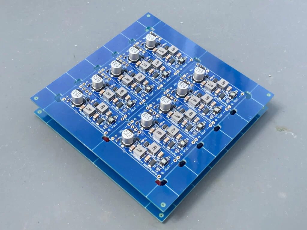
The soldering of the components is now complete.
Cut all the boards along the V-cut line to complete the buck-boost DCDC converter module with brightness sensor.
Measure the characteristics
Let's measure the characteristics of the completed buck-boost DCDC converter .
Measure the input current against the input voltage when the load current is 100mA and 200mA
Measured and calculated, the efficiency is between 70% and 80%. It is almost the same as the simulation by LTSpice at design time. When using a solar cell as a power source, the input voltage is 2 to 5 V, so the efficiency in that range is about 70%.
Since it is a SEPIC circuit that is a modified step-up DCDC converter, it is not very efficient, but I found that it can function normally for both step-up and step-down.
Buck-boost DCDC converter completed!