
World's First Solder Joint Encapsulant Perfect solution for customers looking to eliminate underfilling processes. The SMT 256 Individual Solder Joint Encapsulation Adhesive is the world’s first combined flux gel/individual solder joint encapsulati
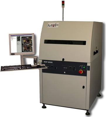
Microelectronics and Semiconductor Inspection. MVP's 850G provides the highest accuracy flip-chip, die assembly inspection. Ensuring the correct placement of the die on the substrate, while providing edge, FM and surface inspection. The 850G modu
Electronics Forum | Mon May 10 11:24:33 EDT 2004 | Charly
Encounter solder ball crack after reflow, found the solder ball is out of shape after reflow, cross section view found that the solder mask opening is not good ( when we do comparason with diff. supplier substrate.) Does the solder mask shape will af
Electronics Forum | Mon May 10 16:37:01 EDT 2004 | davef
First some definitions, the two main types for solder masking near BGA pads are: 1 Pad, Non-Solder Mask Defined. In circuit board design, pads with spacing that does not allow solder (usually bumps) on the pads to contact the adjacent solder mask. [
Industry News | 2012-05-23 14:18:26.0
Joint Industry Guideline Provides Best Practices for Measuring the Strain on Boards and Components During Manufacturing
Industry News | 2018-10-18 08:59:34.0
PRINCIPLE OF SURFACE MOUNT PROCESS(SMT PROCESS)
Technical Library | 2015-02-19 16:54:34.0
Pad cratering is an important failure mode besides crack of solder joint as it’ll pass the regular test but have impact on the long term reliability of the product. A new pin pull test method with solder ball attached and positioning the test board at an angle of 30º is employed to study the strength of pad cratering. This new method clearly reveals the failure mechanism. And a proper way to interpret the finite element analysis (FEA) result is discussed. Impact of pad dimension, width and angle of copper trace on the strength is included. Some findings not included in previous research could help to guide the design for better performance
Technical Library | 2017-06-22 17:11:53.0
C-mode scanning acoustic microscopy (C-SAM) is a non-destructive inspection technique showing the internal features of a specimen by ultrasound. The C-SAM is the preferred method for finding “air gaps” such as delamination, cracks, voids, and porosity. This paper presents evaluations performed on various advanced packages/assemblies especially flip-chip die version of ball grid array/column grid array (BGA/CGA) using C-SAM equipment. For comparison, representative x-ray images of the assemblies were also gathered to show key defect detection features of the two non-destructive techniques.

pcb separator - YSVC 1 http://www.pcbpunchingmachine.com Email?sales@yushunli.com evaliu@yushunli.com http://www.vcutpcbdepaneling.com Website?http://www.hk-yush.com /http://www.pcbdepanelingmachine.com http://www.vcutpcbdepaneling.com / http://www.y
Events Calendar | Mon Mar 16 00:00:00 EDT 2020 - Mon Mar 16 00:00:00 EDT 2020 | ,
BGA & Area Array Failures, Causes & Corrective Actions Online Webinar
crack of solder joint as it'll pass the regular tes
Heller Industries Inc. | https://hellerindustries.com/wp-content/uploads/2018/07/last-will-of-bga-void.pdf
: A total of 21 of 40 test vehicles had a void greater than 45% of solder ball diameter or 20% of ball area Solder crack path typically found at solder joint / BGA package interface Via in Pad (VIP
| http://etasmt.com/cc?ID=te_news_industry,23964&url=_print
(from room temperature to 150°C) Solder paste collapse -- ramp up too fast The solvent in flux cannot vapour thoroughly, so the viscosity of the solder paste will be decreased and cause the paste collapse Soldering ball -- ramp up
winsouce.jpg)
.gif)

.gif)
