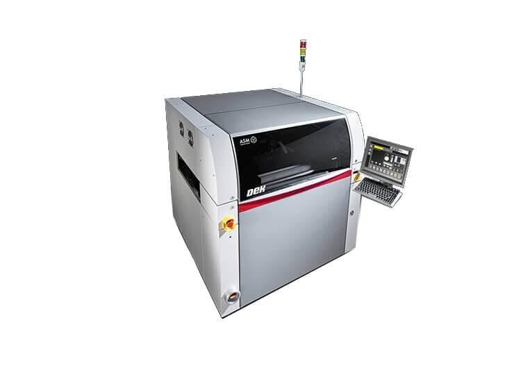
2.0 Cpk @ +/- 12.5µm, (±6 Sigma) * Process Alignment Capability >2.0 Cpk @ +/- 25µm, (±6 Sigma) * Standard cycle time 10 seconds + process Maximum printing surface 508 mm (X) × 508 mm (Y) User interface Touchscreen, keyboard a
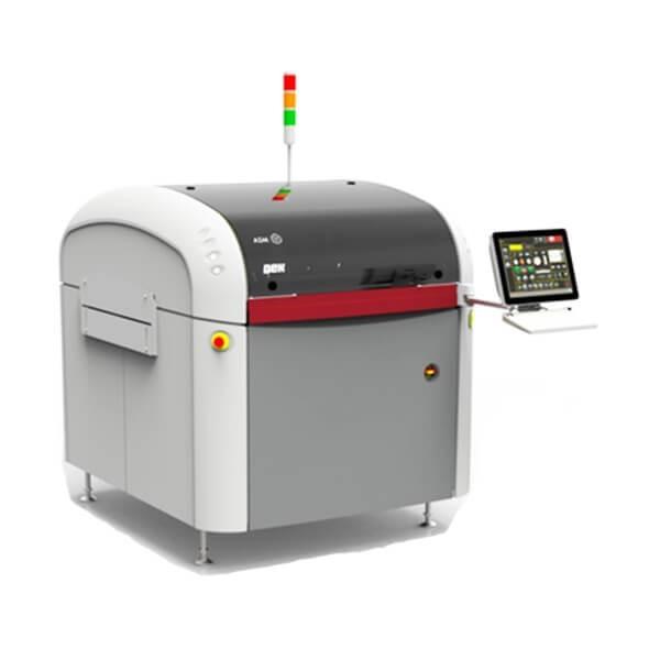
DEK NeoHorizon 03ix SMT Stencil Printer Standard cycle time: 8 seconds + processMaximum printing surface: 510 mm (X) × 508,5 mm (Y)Weight: Approx. 690 kgDEK HawkEye 750 digital cameraProduct description: DEK NeoHorizon SMT Stencil Printer, Standard
Electronics Forum | Thu Aug 24 16:44:27 EDT 2000 | Dr. Ning-Cheng Lee
There is no IMC composition can be identified in phase diagram of In/Sn. There are some compositions such as In3Sn or InSn4 cited in earlier literature. Those composition should be regarded as approximate representation of solid solution of In/Sn. I
Electronics Forum | Sun Mar 30 20:21:44 EST 2003 | iman
we are using a "recommend supplier profile", and we have gotten back to the talking table with them over this profile specs. Thanks for the pointer, have ask them on this issue. Have also asked for their phase-transistion diagram to understand their
Used SMT Equipment | Adhesive Dispensers
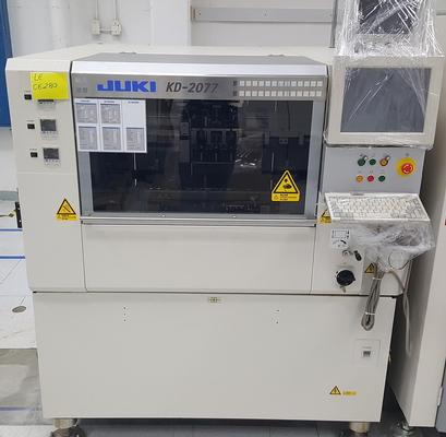
Juki KD-2077 High-Speed Glue Dispenser Brand: Juki Model: KD-2077 Year: 2012 Serial #: 2772A1179 Type:High-Speed Glue Dispenser Machine specifications: Origin: Japan Voltage: 200/220/240/380/400/415V Phase: 3 Hours: 29913.6h Electrical
Used SMT Equipment | General Purpose Test & Measurement
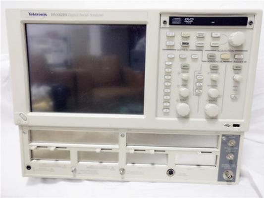
30 dB of Loss Linear Filter for Fixture De-embedding, Linear Filtering TDR (Time Domain Reflectometry) Up to 50 GHz TDR Bandwidth with 15 ps Rejected Rise Time and 12 ps Incident Rise Time Lowest Noise for Accurate Repeatable TDR Measurement Res
Industry News | 2010-04-23 21:51:55.0
BANNOCKBURN, Ill., USA — Celebrating the best of electronic interconnection research being conducted by both industry leaders and academia, IPC – Association Connecting Electronics Industries® announced the 2010 Best Industry Posters and the winners of the second annual IPC Academic Poster Competition at IPC APEX EXPO, held April 6–8, 2010 in Las Vegas.
.jpg)
Parts & Supplies | Pick and Place/Feeders
Supply&Repair JUKI FX-1/FX-1R TWO-PHASE STEPPING MOTOR PN:L900E321000 Model:103H7823-17XE42 Supply all original new juki spare parts. www.greensmt.com SHENZHEN GREEN TECHNOLOGY Company was found in 2003.we are specialized in the field of Indust
Parts & Supplies | Assembly Accessories
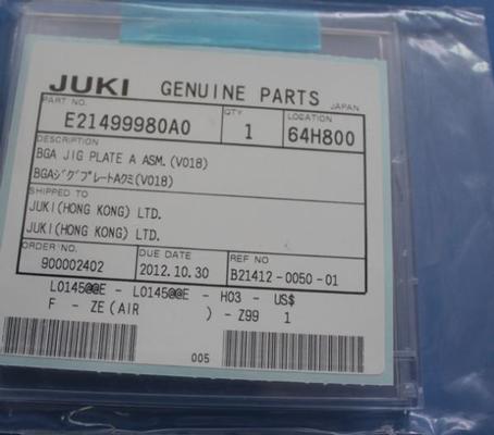
JUKI NGA JIP PLATE A ASM E21499980A0 We are Supply SMT Pick and Place Equipment spare parts(Smt nozzle, Smt Cylinder, Smt Valve, Smt Sensor, Smt Feeder, Smt CPU Board, Smt Laser, Smt driver, Smt ejector……) for Yamaha, JUKI, FUJI ,Panasonic, Samsun
Technical Library | 2020-09-23 21:37:25.0
The need to minimise thermal damage to components and laminates, to reduce warpage-induced defects to BGA packages, and to save energy, is driving the electronics industry towards lower process temperatures. For soldering processes the only way that temperatures can be substantially reduced is by using solders with lower melting points. Because of constraints of toxicity, cost and performance, the number of alloys that can be used for electronics assembly is limited and the best prospects appear to be those based around the eutectic in the Bi-Sn system, which has a melting point of about 139°C. Experience so far indicates that such Bi-Sn alloys do not have the mechanical properties and microstructural stability necessary to deliver the reliability required for the mounting of BGA packages. Options for improving mechanical properties with alloying additions that do not also push the process temperature back over 200°C are limited. An alternative approach that maintains a low process temperature is to form a hybrid joint with a conventional solder ball reflowed with a Bi-Sn alloy paste. During reflow there is mixing of the ball and paste alloys but it has been found that to achieve the best reliability a proportion of the ball alloy has to be retained in the joint, particular in the part of the joint that is subjected to maximum shear stress in service, which is usually the area near the component side. The challenge is then to find a reproducible method for controlling the fraction of the joint thickness that remains as the original solder ball alloy. Empirical evidence indicates that for a particular combination of ball and paste alloys and reflow temperature the extent to which the ball alloy is consumed by mixing with the paste alloy is dependent on the volume of paste deposited on the pad. If this promising method of achieving lower process temperatures is to be implemented in mass production without compromising reliability it would be necessary to have a method of ensuring the optimum proportion of ball alloy left in the joint after reflow can be consistently maintained. In this paper the author explains how the volume of low melting point alloy paste that delivers the optimum proportion of retained ball alloy for a particular reflow temperature can be determined by reference to the phase diagrams of the ball and paste alloys. The example presented is based on the equilibrium phase diagram of the binary Bi-Sn system but the method could be applied to any combination of ball and paste alloys for which at least a partial phase diagram is available or could be easily determined.
Career Center | Gardena, California USA | Engineering
Qual-Pro Corporation provides electronic manufacturing solutions to multiple industries including aerospace, defense, ISR, medical, and precision industrial controls. Our company offers a challenging and rewarding environment with a tremendous opport
Career Center | Houston, Texas USA | Engineering,Management,Production
SMT Manufacturing Engineer – 2nd Shift Hunting Innova is a Houston based company serving industrial, energy, medical, defense and aerospace segments of the Electronic Manufacturing Services (EMS) Industry since 1989. Hunting Innova is located in N
Career Center | Chennai, India | Sales/Marketing
Experience in sales of inter-connect, passive, active, and electro-mechanical components Product Engineering Role as handling BOM, ECO, ECN in the New product introduction of Philips LCD TV and Kulicke and Soffa wire bonding m/c Process and Quali
Career Center | faridabad, India | Engineering,Production,Quality Control
My technical proficiency is extensive and is summarized on my resume (attached). As reflected on my resume (attached) I have completed my B-tech this Year.I am a fresher Electronics Engineer but having 6 months of PCB Assembling,PCB Manufacturing and
Heller Industries Inc. | https://hellerindustries.com/wp-content/uploads/2022/06/Vacuum-Fluxless-Reflow-Technology-for-Fine-Pitch.pdf
. This configuration allows the entire reflow process, 1245 Fig. 2 Oven configuration diagram. Fig. 3 Typical vacuum formic acid reflow profile and its vacuum formic status
GPD Global | https://www.gpd-global.com/co_website/pdf/coating/SimpleCoat-Operation-Guide-23100600.pdf
.............................................................................................. 22 Chapter 6. Programming .................................................................................................................................. 24 1. Diagram design ....................................................................................................................................... 24 2. Setting parameters


winsouce.jpg)