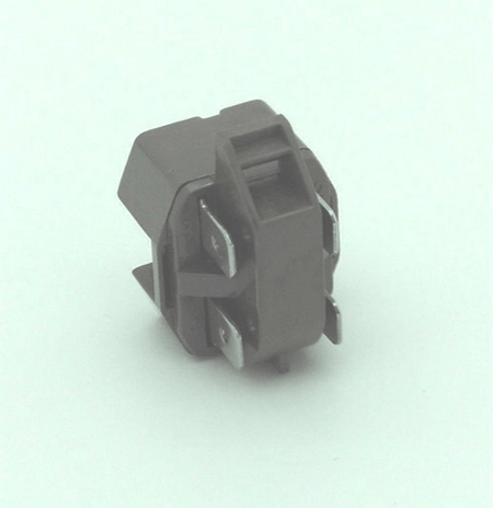
PTC Relay Working Principle
The PTC (positive temperature coefficient) relay is directly connected in series with the secondary winding (start winding) and in parallel with the main winding of the motor. When AC 220V is applied to the two windings, a phase difference will be generated due to phase separation, thus forming an elliptical rotating magnetic field and generating a starting torque to drive the normal operation of the motor.
After that, because the PTC relay is under a high resistance state, the starting circuit is nearly disconnected, and only the running winding drives the motor to run.
PTC relay, also known as contactless starter, is actually a PTC thermistor starter. When starting the compressor, you’ll find the PTC component temperature is low, the resistance is small, and it can be approximated as a straight-through circuit.
If the starting current increases to 4-6 times the normal, it will cause the temperature of the element to rise rapidly. Plus the resistance would increase to several orders of magnitude, and the passing current could become small, which may be regarded as an open circuit.
PTC Relay Wiring Diagram
The connection of the refrigerator PTC relay is relatively simple. Generally, the starter is connected to the compressor.
You should connect one of the compressor power cables to the terminal post on the relay corresponding to the running terminal of the compressor, and the other to the protector.
There are three terminals on both the compressor of the fridge and air conditioner. The terminals R, S, and C mean the run, start, and common respectively. You should connect terminal R with the 220V firing line (L) and PTC relay, S with the other terminal of the relay, C with the zero line (N).

Figure 2: PTC relay wiring diagram.
This article introduces the wiring method of the refrigerator PTC relay, and we hope it will help you in the actual use.
More information please visit OKmarts Industrial Parts Mall (https://okmarts.com/)


