|
Cm System Measurement Principle
Measurement instability is influenced by the dummy types used, accuracy of the glass plate and repeatability and reproducibility of the measurement system.
As a general rule, a measurement tool should be at least 6 to 10 times more accurate than what is being measured. The measurement error of the Cm System is between ���4 ���m for chip components and between ���2 ���m for glass QFP dummies. The suitability of measurement equipment is determined using the relation of measurement instability (Repeatability & Reproducibility) to specification limits of the placement equipment.
Thus, it means the Cm System is able to measure:
- Fine pitch equipment with an accuracy specification up to ��� 20���m (X,Y)
- Chip shooters with accuracy specification up to ��� 40���m (X,Y)
For an optical system to be a capable gauge for evaluating SMT equipment, its accuracy and repeatability must be very high. A GR&R (Gauge Repeatability and Reproducibility) study is an accepted method for evaluating the measurement system performance. The methodology requires that the measurement uncertainty (6 x GR&R error) be at most 25% (10% is preferable) of the specification range of the product being measured. A gauge R&R study was conducted on the Cm System and the %R&R was less than 5%.
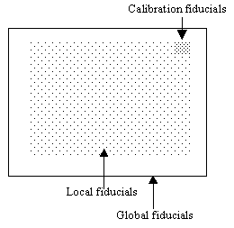
The Cm System uses a self-calibration system which is able to estimate the accuracy of the measurement system (glass plate + optic system). The regular arrangement of the fiducials on the glass plate allows flexibility in the design of the placement program and also for automatic calibration before each measurement.
 Fig. 8: Glass plate fiducials Fig. 8: Glass plate fiducialsThe following table describes the function of the various fiducials on the base plate:
| |
Machine |
Cm System |
| Calibration fiducials |
- |
Fine adjustment of optic system |
| Local fiducials |
Fine adjustment of placement position |
Reference for measurement |
| Global fiducials |
Correction of placement positions |
Correction of measurement position. |
Fig. 9: Function of Fiducials
To achieve a high level of measurement accuracy, it is necessary to have high-resolution camera and lens systems. Therefore, each image created by the camera covers only a small section of the base plate. This means that measurements can be made relative to fixed points (i.e. the fiducials on the base plate and the dummy components), thus cutting down the margin of error caused by the positioning system. The camera must be able to recognize one fiducial on the base plate and one on the dummy component (only for glass QFPs). The distances on the X and Y-axes are measured using a correlation method, which allows for evaluation in sub-pixel units.
Measuring Placement Machine
Before starting a machine capability test, it is necessary to generate a measuring program. This must be done correctly to determine a result as relevant as possible in the minimum amount of time. Test criteria that influenced the results of machine capability are as follows:
- Component type.
- Placement surface.
- Component orientation (X-direction, Y-direction, rotation) and mechanical stress (alternation of short and long distances of robot travel).
- Test of each placement gantry/heads/nozzles and camera.
- Fiducial choice for global and alignment correction.
- Aging time of the machine (usually between one and two hours).
- Lighting system (front light or back light)
- Statistically significant sample size (usually 25 or 30 minimum placement per test)
Sometimes, several different measuring plans have to be tested to arrive at the most relevant and informative one (to identify root causes of machine failure or drifts). Figures 10 and 11 show examples of placement patterns for chip shooters and fine pitch placers.
 Fig. 10: Placement Patterns for Chips(click for larger version) Fig. 10: Placement Patterns for Chips(click for larger version)Figure 10 shows 400 chips for a chip shooter with 20 nozzles (20 components / nozzle), placed at four rotations (0���,90���,180���,270���) and 2 placement directions (left to right and right to left with alternation at the half point of the glass plate).
 Fig. 11: Placement patterns for QFP(click for larger version) Fig. 11: Placement patterns for QFP(click for larger version)Figure 11 shows that 50 QFPs are placed using a fine pitch placer with 5 nozzles (10 components/nozzle), using four rotations before component recognition (0���,90���,180���,270���), and 2 placement directions (left to right and right to left, alternating each row).
After running the measurement program, transmitted light (backlight) is switched on and camera calibration sequence identifies the exact geometric relationship between the camera and the glass plate.
Firstly, the camera moves to the calibration structure (at the top right hand corner of the glass plate) and measures it. If the calibration structure is slightly displaced, the camera analyzes these fiducials in comparison with their nominal position and moves to center it in the field of view. This step optimizes the camera's field of view.
Secondly, the global alignment correction (similar to placement process recognition) is completed. This is the exact identification of the geometric relations between the base plate and the positioning system.
<< Back to Page 2 Page 4 >>

POST A TALKBACK TO THIS ARTICLE!
The SMT Express is brought to you by SMTnet.
|